
The 3 Phase Current Transformer is a critical component used in electrical systems to accurately measure currents across all three phases. This transformer plays a pivotal role in various applications, including energy monitoring, power quality analysis, and equipment protection. Engineered with precision and durability in mind, the 3 Phase Current Transformer ensures reliable performance even in demanding industrial environments. Its compact design and versatile installation options make it suitable for a wide range of commercial and industrial applications. With its ability to provide accurate measurements and real-time data, the 3 Phase Current Transformer contributes to the efficient operation and safety of electrical systems. Trust in the reliability and performance of the 3 Phase Current Transformer for your power monitoring needs.
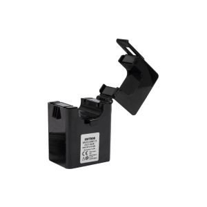
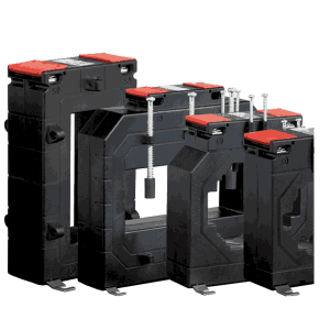
Rish 3 Phase CTs are rectangular type and encapsulated with UL94V-0 approved polycarbonate. Metering 3 phase CTs feature with wire sealable terminal covers & wide range of primary current ratings.
3-Phase Current Transformers
LOW VOLTAGE CURRENT TRANSFORMER
Characteristic Parameters
Current transformers convert an alternating current usually high in to a proportional lower one,
depending on their use. Measurement type CTs are required to transform the primary current, at various classes of
accuracy, as specified by the class designation, over a current range from 1 to 120 percent of its rated primary ratio.
The design of this type of transformer requires the inclusion of a core and winding which will when connected to its
rated burden; perform within the limits of error as indicated by the standard’s specification. It is an advantage for a
measurement type transformer to saturate above this range, which provides a protection against damage to
instruments by limiting the secondary current when surge currents or faults appear in the primary circuit.
Current transformer: – An instruments transformer in which the secondary current, in normal condition of use, is
substantially proportional to the primary current and differs in phase it by an angle which is approximately zero for an
appropriate direction of connections.
Measuring transformer: – A current transformer intended to supply indicating instruments integrated meter, relay
and similar apparatus.
Protective Current Transformer: – Acurrent transformer intended to supply protective relays.
Rated transformation ratio: -The ratio of the rated primary current to the rated secondary current.
Rated primary current: – The value of primary current which appears in the designation of the transformer and on
which the performance of the currant transformer is based.
Rated secondary current: – The value of secondary current which appears in the designation of the transformer
and on which the performance of the currant transformer is based.
Current error (ratio error):– The error with a transformer introduces into the measurement of a current and which
arises from the fact that actual transformation ratio is not equal to the rated transformer ratio.
The current error expressed in percentage is given by the formula:
Current error, percent = (Ka.Is-Ip) x 100 / Ip
Where Ka= rated transformation ratio
Ip= actual primary current
Is= actual secondary current when Ip is flowing under the conditions of measurement
Accuracy Limit Factor (ALF): -The ratio of the rated accuracy limit primary current to the rated primary current.
Phase displacement: – the difference in phase between the primary and secondary current vectors, the direction of
the vectors being so chosen that the angle is zero for the perfect transformer. The phase displacement is said to be
positive when the secondary current vector leads the primary current vector. It is usually express in minutes.
Composite Error: – Composite error is the resulting limitation of the harmonic content of the secondary current
which is necessary for the correct operation of certain types of relays.
Accuracy class: – A designation assigned to a current transformer the errors of which remain within specified limit
under prescribed conditions of use.
Burden: -The impedance of the secondary circuit in ohms and power factor.
Rated burden: -The impedance of the secondary circuit on which the accuracy
requirements are based. It is usually expressed as apparent power (in VA), at the rated secondary current and at a
specified power factor.
Rated output :– The value of the apparent power (in volt-amperes at a specified power factor) which the current
transformer is intended to supply to the secondary circuit at the rated secondary current and with rated burden
connected to it.

Reviews
There are no reviews yet.