Cable Tray Fill Calculation: BS 8519 / IEC 61537 Method
How to calculate cable tray fill: cross-section ratio, ampacity derating, weight check, and segregation rules. Worked example for a typical industrial routing.
Cable tray fill is governed by two limits — cross-sectional area ratio (typically 40% maximum) and ampacity derating from grouped cables. Get either wrong and the tray either overheats and fails to BS 8519, or the cables sized for free air run hot under their actual installation conditions. This guide covers both checks with a worked example.
Check 1 — Cross-section area ratio
Sum the outer-diameter areas of every cable in the tray, then check the ratio against tray usable area:
Related Products
Cable Systems
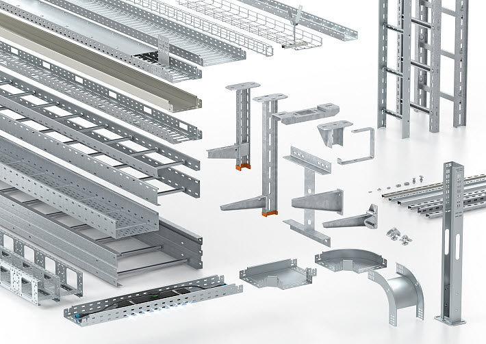
Paneltech Systems offers comprehensive cable management systems for efficient, secure and organised cable setups across industrial and commercial environments.
View Product
Marine Cables
Heavy-duty marine-grade cables designed for reliable performance in marine and offshore electrical installations.
View Product
ATS / MTS Kenya
ATS/MTS solutions from Paneltech Systems provide reliable Automatic and Manual Transfer Switches for seamless power transfer in industrial and commercial electrical systems.
View Product
LED Lights
Paneltech Systems offers high-quality LED lighting solutions for indoor and outdoor applications ÔÇö bright, energy-efficient lighting for commercial and industrial spaces.
View ProductFill ratio = Σ(π × OD² / 4) / (W × H)
Where W is the usable tray width (clear width between side rails) and H is the maximum cable depth (usually the tray height for ladder, or 75% for solid bottom). Typical industry limits:
| Tray type | Max fill ratio | Reason |
|---|---|---|
| Ladder (open bottom) | 40% | Allows airflow around cables |
| Perforated | 35% | Some restricted airflow at bottom |
| Solid-bottom | 30% | No airflow under cables |
| Wire basket (vented) | 40% | Best airflow but limited depth |
Check 2 — Ampacity derating from grouped cables
Cables in free air dissipate heat to surrounding air. When stacked or bunched in a tray, mutual heating reduces the safe ampacity. IEC 60364-5-52 Table B.52.21 gives correction factors:
| Number of circuits in tray | Touching (multilayered) | Spaced 1× cable diameter |
|---|---|---|
| 1 | 1.00 | 1.00 |
| 2 | 0.85 | 0.95 |
| 3 | 0.79 | 0.92 |
| 4–6 | 0.72 | 0.85 |
| 7–9 | 0.69 | 0.81 |
| 10–12 | 0.66 | 0.78 |
| ≥13 | 0.63 | 0.75 |
For cables touching each other in a single layer on a ladder tray, factors are slightly more generous than the multilayered values. The exact table choice depends on the cable arrangement.
Check 3 — Mechanical weight load
Calculate cable weight per metre and check against the tray's span rating. Typical industrial PVC-insulated copper cables weigh roughly:
- 4-core 35 mm² LSZH: ~2.1 kg/m
- 4-core 95 mm² XLPE: ~4.8 kg/m
- 3-core 300 mm² XLPE: ~12 kg/m
- Single-core 630 mm² aluminium: ~3.5 kg/m
A 600 mm tray with 50 mixed-size cables might carry 80–120 kg/m. Verify the tray manufacturer's safe working load at the proposed support spacing — usually 1.5–2 m for steel ladder trays.
Segregation rules
- Power and instrumentation: Minimum 300 mm separation, or a metallic earthed divider plate. EMC interference into 4–20 mA loops is the main concern.
- Power and data (LAN, fibre): 300 mm minimum, more if cables are parallel for long runs. Use shielded data cable in the vicinity of large motors.
- Fire-resistant and standard cables: Separate trays per BS 5839 / IEC 60331. Fire-survival cables must be on their own routing.
- LV and ELV: Separate trays preferred; same tray acceptable only with a divider plate.
Worked example — process plant ladder run
| Parameter | Value |
|---|---|
| Tray | 600 × 100 mm steel ladder, hot-dip galvanised |
| Cables in tray | 12 × 4-core 50 mm² XLPE motor feeders (OD = 28 mm), plus 3 × 7-core 1.5 mm² instrumentation (OD = 14 mm) |
| Span | 1.8 m between supports |
Fill ratio check:
- Cable cross-section: 12 × (π × 28² / 4) + 3 × (π × 14² / 4) = 12 × 615.7 + 3 × 153.9 = 7388 + 462 = 7850 mm²
- Tray usable area: 600 mm × 100 mm = 60,000 mm²
- Fill ratio: 7850 / 60,000 = 13.1% — well within 40% limit ✓
Ampacity check:
- 12 circuits touching in single layer: derating factor ≈ 0.75
- Cable rated 152 A free-air → 152 × 0.75 = 114 A actual ampacity in this tray
- If feeder breaker is 125 A, cable is undersized — step up to 70 mm² (177 A × 0.75 = 133 A) to keep margin
Weight check:
- 12 × 2.6 kg/m + 3 × 0.4 kg/m = 32.4 kg/m
- Manufacturer SWL at 1.8 m span: typically 75 kg/m for this tray section — comfortable ✓
Segregation note: Instrumentation cables should ideally be in a separate tray, or behind a divider plate, or specified with overall screening. For this example, switching to overall-screened 7-core instrumentation cable resolves the EMC concern.
Common mistakes
- Calculating fill ratio without leaving space for future cables — design for 25% fill if expansion is likely
- Ignoring derating — installer sizes cable to free-air ampacity, then runs hot under actual load
- Mixing power and instrumentation without segregation — intermittent process upsets that defy diagnosis
- Forgetting cable weight — tray sags or rivets fail at the supports
Bottom line
Cable tray fill is a 3-step calculation: cross-section ratio, ampacity derating, mechanical weight. All three are quick once the cable schedule is final. Allow generous spare capacity, choose the right tray type for the airflow your loads need, and segregate power from instrumentation. The cost of an oversized tray is small; the cost of replacing it later is not.
See our electrical supplies range including cable trays, ladders, and tray accessories for projects across Kenya.