Single-Line Diagrams: What Every Electrical Drawing Must Include
The single-line diagram (SLD) is the most important electrical drawing on a project. This guide covers what every SLD must show, common omissions, the IEC standard symbology, and how to read one for coordination, protection, and load-flow purposes.
A single-line diagram (SLD) is a simplified representation of an electrical power system that uses one line to depict what is, in reality, a three-phase circuit. The SLD is the master drawing on every electrical project — every load calculation, protection coordination study, fault analysis, and panel build references it. If the SLD is incomplete or wrong, every downstream activity inherits its errors. This guide explains what every SLD must include, the IEC 60617 symbol conventions, common omissions, and how to read one for the three most common engineering activities.
What a single-line diagram must include
An SLD is not just a "block diagram with names." A complete SLD includes:
Related Products
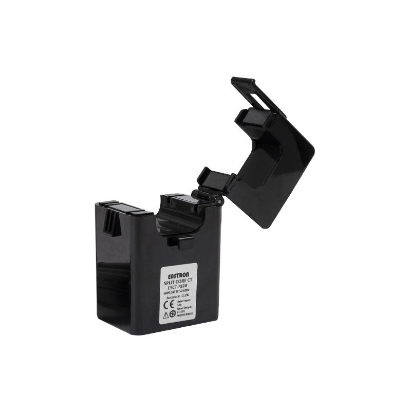
Single Phase RJ12 CT
Single Phase RJ12 current transformer for precise single-phase current measurement in power monitoring and metering applications.
View Product
Light Accessories
A comprehensive range of lighting accessories for commercial and industrial electrical installations.
View Product
Switches and Sockets
Quality switches and sockets for residential, commercial and industrial electrical installations.
View Product
ATS / MTS Kenya
ATS/MTS solutions from Paneltech Systems provide reliable Automatic and Manual Transfer Switches for seamless power transfer in industrial and commercial electrical systems.
View Product- Every source of supply — utility incomer, generator(s), UPS, solar inverter — with rated voltage, capacity, and fault contribution.
- Every transformer — rated kVA, primary/secondary voltage, impedance (%Z), vector group, and tap range.
- Every switching device — breakers (with frame and trip ratings), switches, contactors, disconnects. Show the protection relay type and settings beside the device.
- Every busbar — rated current, fault withstand (kA for 1s), labelling.
- Every cable — size, conductor (Cu/Al), insulation type, length where known, route reference.
- Every load — connected kW, demand factor, design current. Group sub-DB loads where individual circuits aren't shown but the demand is summed.
- Earthing arrangement — TT, TN-S, TN-C-S, IT — clearly labelled, with earthing electrode locations shown.
- Metering points — utility kWh meters, sub-metering points, measurement transformers (CTs/VTs with ratios).
- Protection scheme — relay types (ANSI codes 50, 51, 87, 27, 81, etc.), interlocks, lockout relays, busbar protection where applicable.
- Tie breakers and bus couplers — with normally-open / normally-closed status clearly indicated.
IEC 60617 symbol conventions
Engineers in Kenya, East Africa, and most of the world outside North America use IEC 60617 symbols. The most common ones:
| Element | IEC 60617 symbol | Common ANSI alternative |
|---|---|---|
| Circuit breaker, drawout | Rectangle with diagonal line, X above | Square with crosshair |
| Moulded-case CB | Rectangle with diagonal line | Similar |
| Fuse | Rectangle | Squiggle |
| Switch-disconnector | Switch symbol with line through | Similar |
| Transformer 2-winding | Two interlocked circles | Two interlocked circles |
| Generator | Circle with G | Circle with G |
| Motor | Circle with M | Circle with M |
| Earth | Three horizontal lines, decreasing width | Similar |
| CT | Two parallel arcs across the line | Bowtie |
| VT (PT) | Two interlocked circles smaller than transformer | Similar |
Reading an SLD for protection coordination
To coordinate protection, walk the SLD upstream-to-downstream:
- Find the worst-case fault at each bus. SLD gives source impedance + transformer %Z + cable impedance — you can hand-calculate or feed an ETAP / SKM file.
- Confirm the breaker at each level has interrupting rating ≥ that fault current.
- For each pair of upstream/downstream breakers, plot their time-current curves. The upstream breaker's curve must lie above and to the right of the downstream — meaning for any fault, the downstream device clears first.
- Where curves cross or overlap, either change device ratings, change settings, or accept partial selectivity with documentation.
An SLD that doesn't show fault levels at each bus and protection settings beside each device cannot support a coordination study without significant supplementary information.
Reading an SLD for load flow
The SLD lets you trace the path from any load to the source(s) and sum currents on each segment.
- For each load, identify the connected kW and demand factor.
- Convert to current at the relevant voltage and power factor.
- Sum currents from terminal to feeder to sub-DB to main panel to incomer.
- Compare each segment's current against its rated cable / busbar / breaker. Flag any that are over-utilised.
- Repeat for the worst-case combination of loads — usually peak day with all critical loads running.
Reading an SLD for arc-flash and personnel safety
Arc-flash energy at any point depends on bolted fault current and clearing time at that point. The SLD provides both:
- Source impedance and topology give bolted fault current
- Protection settings give clearing time
Modern arc-flash calculations follow IEEE 1584. An SLD with documented protection settings supports this calculation; an SLD without settings cannot.
Common omissions on SLDs
- Protection settings missing — the SLD shows a breaker but no setting values. Coordination is impossible without them.
- Fault levels not stated at each bus — without these, the consulting engineer can't verify equipment ratings.
- Earthing arrangement not labelled — implicit TN-S assumption when the site is TT (or vice versa) leads to incorrect calculations on residual current devices.
- Metering CTs without ratios — instrument inputs can't be calibrated without ratio information.
- Cable lengths and types omitted — voltage drop and short-circuit calculations need both.
- Generator paralleling shown without synchronisation interlocks — operationally unsafe, indicates the SLD wasn't reviewed.
- Standby supply shown with no transfer device — the actual operational behaviour is unclear.
- Different "normal" and "alternate" topology shown on different sheets — operations confusion guaranteed.
SLD vs three-line diagram vs schematics
- Single-line diagram — one line per three-phase circuit. Used for system overview, coordination, fault studies.
- Three-line diagram — shows all three phases (and neutral) individually. Used where phase-specific protection or unbalance matters (e.g., dispersed solar PV with single-phase inverters).
- Schematics / wiring diagrams — show every conductor and every terminal on a single device or panel. Used by the assembly shop and the commissioning electrician.
An SLD is necessary but not sufficient. A full set of drawings on any real project includes the SLD, the schematics for each panel, the layout drawings, the cable schedule, and the earthing layout.
What the SLD looks like at sign-off
A sign-off SLD on a real project should:
- Be on a single sheet where the site permits — multi-sheet SLDs lose information at sheet boundaries
- Be drawn to a clear hierarchy: utility at top, generation top-right, distribution centre-left, loads at the bottom
- Have a title block including project name, drawing number, revision, drawn-by, checked-by, approved-by, date
- Be issued as PDF (immutable) and as the source CAD file (DWG or EPLAN)
- Have the most recent revision noted in the title block AND in the drawing
Bottom line
A single-line diagram is the most important drawing on a project. Get it right and every coordination, load-flow, and fault analysis is straightforward. Get it wrong or leave it incomplete and the team is fighting fragmented information for the project's lifetime. Specify SLD completeness in the consultant's terms of reference — and refuse to sign off on a drawing that's missing protection settings, fault levels, or earthing labels.
See our design and engineering service for SLD development, coordination studies, and CAD-based as-built documentation on Kenyan projects.