Earthing System Kenya: TN-S, TN-C-S and TT Explained
An earthing system Kenya installation uses provides a controlled path for fault current and helps protective devices operate safely. Learn how TN-S, TN-C-S and TT arrangements differ

TN-S, TN-C-S and TT are different earthing arrangements that define how the electrical supply, protective conductor and earth electrode are connected. Choosing the correct arrangement affects fault-current paths, protective-device operation, touch-voltage control and overall electrical safety.
Earthing is one of the most important parts of an electrical installation, yet it is often misunderstood.
Related Products

ATS / MTS Kenya
ATS/MTS solutions from Paneltech Systems provide reliable Automatic and Manual Transfer Switches for seamless power transfer in industrial and commercial electrical systems.
View Product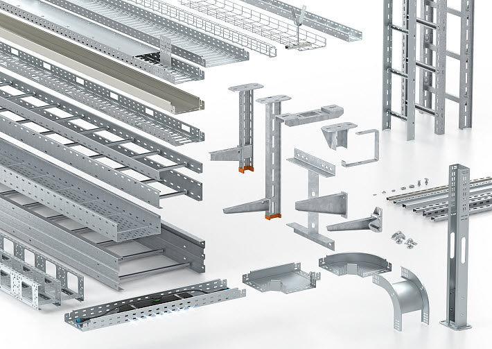
Cable Systems
Paneltech Systems offers comprehensive cable management systems for efficient, secure and organised cable setups across industrial and commercial environments.
View Product
3 Phase Current Transformer
3-Phase Current Transformers for accurate power monitoring and measurement. Paneltech Systems offers high-quality Rishabh 3-Phase CTs for industrial energy monitoring and protection.
View Product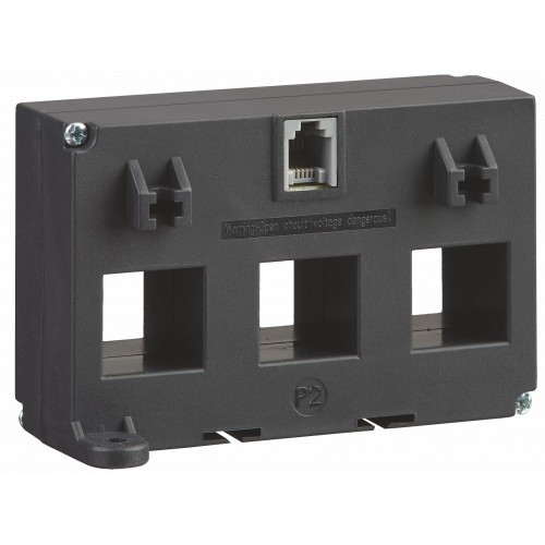
3 Phase RJ12
3-Phase RJ12 from Paneltech Systems for accurate power monitoring and efficient current measurement in industrial applications.
View ProductA good earthing system is not simply a copper rod driven into the ground. It is an engineered system involving the supply arrangement, protective conductors, bonding, earth electrodes and protective devices.
For Kenyan installations, the applicable supply conditions, project specifications, utility requirements and relevant standards should be confirmed by a qualified electrical professional.
What Is an Earthing System?
An earthing system connects appropriate parts of an electrical installation to earth and establishes a defined path for fault currents. Its purpose is to help limit dangerous voltages and allow protective devices to disconnect faulty circuits.
An installation can contain several related components:
- Earth electrode
- Protective conductor
- Main earthing terminal
- Main bonding conductors
- Circuit protective conductors
- Neutral conductor
- Protective devices
These components work together.
The basic objective is:
Fault occurs
↓
Fault current flows through the intended protective path
↓
Protection detects the fault
↓
Circuit disconnects
This helps reduce the risk of electric shock and equipment damage.
What Do TN-S, TN-C-S and TT Mean?
The letters identify how the source and exposed conductive parts of the installation are connected to earth. In TN systems, the supply has a direct connection to earth and exposed conductive parts are connected to that earthed source through protective conductors; TT systems use a separate local earth electrode for the installation.
The terminology is:
- T — direct connection to earth
- N — exposed conductive parts connected to the earthed supply point
- S — neutral and protective functions are separate
- C — neutral and protective functions are combined
This gives us:
TN-S
Separate neutral and protective conductors.
TN-C-S
Combined neutral/protective conductor for part of the supply, then separated into neutral and protective conductors.
TT
The installation uses its own earth electrode, independent of the supply protective-earth arrangement.
TN-S Earthing System
In a TN-S system, the neutral conductor and protective earth conductor remain separate throughout the relevant installation. This arrangement provides a dedicated protective conductor for fault-current paths.
A simplified arrangement is:
Transformer
↓
Neutral — N
Protective Earth — PE
↓
Installation
The PE conductor connects exposed conductive parts to the source earthing point.
Key characteristics
- Separate N and PE
- Dedicated protective conductor
- Defined fault-current path
- No PEN conductor within the relevant installation
TN-S can provide a straightforward arrangement for installations where the supply infrastructure supports it.
TN-C-S Earthing System
TN-C-S combines the neutral and protective functions in a PEN conductor for part of the supply and separates them into neutral and protective conductors at a defined point. After separation, the conductors must be treated as separate functions.
The simplified arrangement is:
Supply
↓
PEN
↓
Separation point
↙︎ ↘︎
N PE
↓
Installation
This arrangement is commonly encountered in distribution systems where the supply network uses a combined conductor before the installation's separation point.
The exact arrangement must follow the requirements of the supply network and applicable standards.
TT Earthing System
A TT system connects the installation's exposed conductive parts to a local earth electrode, while the supply has its own earth connection. Fault protection therefore depends strongly on the installation earthing electrode, bonding and appropriate protective devices.
A simplified arrangement is:
Supply transformer
↓
Supply earth
↕Earth
↕Local installation electrode
↓
Protective conductors
↓
Exposed conductive parts
The local electrode becomes an important part of the fault-protection arrangement.
Residual-current protection is commonly important in TT systems because the earth-fault current may not be high enough to operate conventional overcurrent protection quickly.
TN-S vs TN-C-S vs TT
The major difference is the relationship between the neutral, protective conductor and earth electrode. TN-S keeps N and PE separate, TN-C-S uses a combined PEN conductor before separation, while TT relies on a local installation earth electrode.
| Feature | TN-S | TN-C-S | TT |
|---|---|---|---|
| Neutral/PE | Separate | Combined then separated | Separate |
| PEN conductor | No | Yes, upstream of separation | No |
| Local earth electrode | May be present | May be required/used depending on system | Fundamental |
| Fault-current path | PE to source | PE/PEN to source | Through earth electrodes |
| RCD importance | Application dependent | Application dependent | Particularly important |
| Supply arrangement | Defined by network | Defined by network | Local installation electrode |
This table is a simplified explanation. Actual design requirements depend on the installation and supply system.
Why Earthing Matters
Earthing helps control dangerous fault voltages and provides a path for fault current so that protective devices can disconnect defective circuits. Effective earthing is therefore part of the installation's overall protection against electric shock and electrical faults.
Consider a metal enclosure connected to a live conductor because of insulation failure.
Without an appropriate protective path:
Live conductor contacts enclosure
↓
Enclosure can become hazardous
↓
Person touches enclosure
↓
Potential electric shock
With an appropriate protective system:
Live conductor contacts enclosure
↓
Fault current flows through protective path
↓
Protection operates
↓
Supply disconnects
The protective system must be designed so that this sequence occurs reliably.
Earthing Is Not the Same as Bonding
Earthing connects an installation to earth, while bonding connects conductive parts together to reduce dangerous potential differences. Both functions are important but they are not interchangeable.
Earthing
Provides a connection to earth.
Bonding
Connects conductive parts together.
Bonding can involve:
- Metallic water services
- Structural metalwork
- Other extraneous conductive parts
The exact bonding requirements depend on the installation.
Protective Earth vs Neutral
The neutral conductor carries normal operating current, while the protective earth conductor is primarily intended to carry fault current and maintain exposed conductive parts at a safe potential. They should not be treated as interchangeable conductors.
Neutral
Normal operation:
Load → Neutral → Source
Protective Earth
Fault condition:
Fault → PE → Source → Protective device operates
This distinction is fundamental to safe electrical design.
What Is a PEN Conductor?
A PEN conductor combines the protective and neutral functions in part of a TN-C or TN-C-S system. Because it performs two safety-critical functions, its design, continuity and separation requirements are particularly important.
PEN means:
Protective Earth + Neutral
At the appropriate separation point:
PEN → PE + N
After separation, the PE and neutral conductors should not be casually reconnected downstream.
What Happens if a PEN Conductor Fails?
A loss or poor connection of a PEN conductor can create serious safety conditions because the conductor carries both neutral and protective functions. The installation therefore requires appropriate design, bonding and protective measures to manage this risk.
A PEN problem can potentially result in:
- Neutral displacement
- Unexpected voltages
- Energised exposed metalwork under fault conditions
- Equipment damage
This is one reason why TN-C-S systems require careful engineering.
TT Earthing and Earth Resistance
In a TT installation, the resistance of the installation's earth electrode contributes directly to the fault-protection arrangement. The electrode system must therefore be designed and tested to achieve the required protective performance.
Factors affecting electrode performance include:
- Soil resistivity
- Electrode type
- Electrode length
- Number of electrodes
- Electrode spacing
- Soil moisture
- Seasonal conditions
- Connection quality
A single earth rod is not automatically sufficient for every installation.
Soil Conditions in Kenya
Kenyan soil conditions vary considerably between locations, so earth-electrode performance cannot be assumed from one site to another. Earth resistance should be measured at the actual installation rather than relying solely on theoretical assumptions.
Conditions can vary due to:
- Soil type
- Moisture
- Rock
- Clay
- Sand
- Groundwater
- Seasonal rainfall
A site investigation can help determine the appropriate earthing approach.
Earth Electrode Testing
Earth electrode testing verifies the resistance and effectiveness of the earthing system. Testing should use an appropriate method and instrument for the installation being assessed.
Common methods include:
- Fall-of-potential testing
- Three-point testing
- Clamp-based testing where applicable
- Other approved measurement techniques
The selected test method depends on the installation configuration.
Testing should be documented.
What Earth Resistance Value Is Required?
There is no single earth-resistance value that automatically makes every electrical installation safe. The required value depends on the earthing arrangement, protective-device characteristics, installation design and applicable requirements.
This is particularly important with TT systems.
For a TT system, the relationship between:
- Earth electrode resistance
- Residual-current protection
- Touch voltage
- Disconnection requirements
must be considered together.
Therefore, simply saying “the earth must be below X ohms” without considering the protection arrangement can be misleading.
RCDs and Earthing Systems
Residual-current devices can provide important additional protection by detecting current imbalance between conductors and disconnecting the circuit when leakage exceeds the device's operating threshold. Their role is particularly significant in TT installations.
An RCD monitors current balance.
Normally:
Current out ≈ Current back
During an earth leakage fault:
Current out ≠ Current back
The RCD detects the difference and can disconnect the circuit.
RCD protection does not replace proper earthing.
It complements the earthing and protective system.
Earthing and Circuit Breakers
Circuit breakers and fuses protect primarily against overcurrent conditions, while the earthing system establishes the fault-current path that helps protection operate. The two functions must therefore be designed together.
A simplified fault path is:
Phase → Faulted metalwork → PE → Source
If the fault loop impedance is too high, the fault current may be insufficient to operate an overcurrent protective device within the required time.
This is why fault-loop performance matters.
Earth Fault Loop Impedance
Earth fault loop impedance represents the impedance of the complete path followed by fault current from the source through the fault and back to the source. Its value affects the magnitude of fault current and therefore protective-device operation.
A simplified loop is:
Source
↓
Phase conductor
↓
Fault
↓
Protective conductor
↓
Source
The lower the loop impedance, the greater the potential fault current for a given supply voltage.
The designer must verify that the protective device can disconnect within the required time.
Main Earthing Terminal
The main earthing terminal provides a central connection point between the installation's protective conductors, earthing arrangements and relevant bonding conductors. It forms an important part of the installation's protective system.
Depending on the installation, it can connect:
- Main protective conductor
- Circuit protective conductors
- Earth electrode conductor
- Bonding conductors
- Other permitted earthing connections
The arrangement should be clearly identified and documented.
Earthing in Electrical Panels
Electrical panels should have appropriate protective-earth connections to their metal enclosures and accessible conductive parts. The protective conductor should be continuous and correctly terminated.
Panel checks should include:
- Earth bar
- Earth conductor
- Door bonding where required
- Enclosure continuity
- Cable gland bonding where applicable
- Incoming PE connection
- Outgoing circuit PE connections
Painted surfaces and removable doors require appropriate attention during panel construction.
Earthing and Cable Glands
Cable gland selection can affect the protective-earth arrangement, particularly with metallic cables, armoured cables and metallic enclosures. The gland and termination system should provide the required mechanical and electrical continuity.
Depending on the cable system, this may involve:
- Armouring
- Earth tags
- Bonding connections
- Gland plates
- Earth continuity conductors
The correct arrangement depends on the cable construction and installation design.
Common Earthing Mistakes
Common earthing mistakes include undersized protective conductors, poor connections, incorrect neutral-earth links, inadequate bonding and assuming that a low earth-electrode resistance alone guarantees safety.
Mistake 1: Treating Earth as a Backup Neutral
PE should not carry normal load current.
Mistake 2: Random Neutral-Earth Connections
Incorrect downstream bonding can create dangerous circulating currents and defeat the intended system arrangement.
Mistake 3: Ignoring Connections
A good earth electrode is of little value if the conductor or termination is defective.
Mistake 4: Testing Only the Electrode
The complete protective system must be considered.
Mistake 5: Using the Same Design Everywhere
Different supply arrangements require different approaches.
TN-S, TN-C-S or TT: Which One Should You Use?
The earthing arrangement is not normally chosen in isolation by the building owner; it depends significantly on the electrical supply arrangement available and the applicable installation requirements. The designer should confirm the supply earthing system before designing the installation.
A practical process is:
Confirm supply arrangement
↓
Identify applicable requirements
↓
Assess installation characteristics
↓
Design protective conductors and bonding
↓
Select protective devices
↓
Verify fault protection
↓
Test and document
For a utility-connected installation, the supply provider's requirements should also be considered.
Earthing for Industrial Installations
Industrial installations often require more detailed earthing design because they can contain large motors, transformers, generators, VFDs, metallic structures and extensive cable networks. The earthing system should account for both electrical safety and operational requirements.
Consider:
- Main LV switchboards
- Transformers
- Motors
- MCCs
- Generators
- VFDs
- Cable trays
- Structural steel
- Lightning protection
- Surge protection
These systems should be coordinated rather than designed independently.
Earthing and Lightning Protection
Lightning protection and electrical installation earthing are related but should not be treated as identical systems. Lightning protection requires its own engineered design, bonding and coordination with the building's electrical protection strategy.
A complete project may need to consider:
- Lightning protection system
- Main earthing system
- Equipotential bonding
- Surge protection devices
- Electrical installation earthing
Coordination helps reduce dangerous potential differences and equipment damage.
Earthing and Surge Protection
Surge protection devices require an appropriate connection to the protective system so that transient overvoltages can be diverted effectively. Long or poorly arranged connections can reduce SPD performance.
SPD installation should consider:
- Conductor length
- Conductor routing
- Protective device coordination
- Earthing arrangement
- Equipment location
- Surge exposure
Earthing and surge protection should therefore be considered together during design.
Testing an Earthing System
Commissioning should verify continuity, earth-electrode performance where applicable, protective-device operation and other required parameters. Results should be recorded as part of the installation's commissioning documentation.
Depending on the installation, tests can include:
- Protective conductor continuity
- Earth electrode resistance
- Insulation resistance
- Polarity
- Earth fault loop impedance
- RCD operation
- Functional testing
Testing requirements should follow the applicable standards and project specifications.
Why Documentation Matters
Accurate earthing documentation helps maintenance teams understand how the protective system is arranged and where important connections are located. It also makes future modifications safer and easier to verify.
Documentation can include:
- Earthing schematic
- Single-line diagram
- Earth-pit layout
- Electrode details
- Test results
- Bonding schedule
- Protective conductor sizes
- Main earthing terminal details
Changes to the electrical installation should be reflected in the documentation.
Paneltech Systems Earthing and Electrical Engineering
Paneltech Systems Ltd can incorporate protective earthing, bonding and electrical protection considerations into electrical panel and distribution projects. The final earthing arrangement should always be established from the project's supply conditions, applicable standards and engineering requirements.
Potential project areas include:
- LV switchboards
- Distribution panels
- MCC panels
- Electrical protection
- Earthing coordination
- Surge protection
- Industrial automation
- Electrical testing
Explore Paneltech Systems for electrical engineering and panel solutions.
You can also review the Paneltech Systems Knowledge Site for technical resources.
Final Earthing Checklist
A safe earthing system requires more than an earth electrode: the supply arrangement, protective conductors, bonding, fault paths, protective devices and testing must work together. TN-S, TN-C-S and TT systems should therefore be selected and verified as complete protection arrangements.
Before commissioning an installation, confirm:
- Supply earthing arrangement
- TN-S, TN-C-S or TT configuration
- Main earthing terminal
- Protective conductor continuity
- Bonding
- Earth electrode arrangement
- Earth resistance where applicable
- Fault-loop performance
- RCD protection where required
- Circuit-breaker coordination
- Panel earth connections
- Cable termination
- Lightning protection coordination
- Surge protection
- Test results
- Updated drawings
The key principle is simple: earthing is a complete electrical safety system, not just an earth rod.
For Kenyan projects, the final design should be checked against the applicable Kenyan regulations, utility requirements and relevant IEC standards by a competent electrical professional.