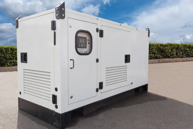
Fire Pump Controller Kenya: 2026 Standards and Specs | Paneltech Systems Kenya
Need a fire pump controller Kenya? Compare compliant pump panels, EN 12845 requirements, specifications, monitoring and fire-safety controls.
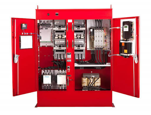
A fire protection system is only as dependable as its ability to deliver the required water when a fire occurs. In a sprinkler or fire hydrant installation, the fire pump controller panel is responsible for controlling and monitoring the fire pump and ensuring that the pump can respond reliably when pressure falls or a fire protection demand occurs.
A fire pump controller Kenya installation must therefore be designed differently from an ordinary motor starter. It has to account for automatic starting, reliable power supply, pressure detection, manual operation, fault indication, testing and the standards applicable to the specific fire protection system.
Related Products

Protection Panels
Robust protection panels safeguarding electrical systems and equipment from faults, overloads and short circuits.
View Product
Feeder Pillar Panels
Feeder pillar panels providing reliable power distribution solutions for outdoor and indoor industrial and commercial applications.
View Product
PLC Automation Panels
Advanced PLC automation panels for intelligent control of industrial processes, tailored to your operational requirements.
View Product
Panels For Data Centers
Specialised low voltage panels designed for data centre power distribution, ensuring high reliability and redundancy.
View ProductFor Kenyan commercial buildings, warehouses, factories, hospitals, apartments and industrial facilities, selecting the controller should be part of the overall fire protection engineering process rather than treated as a simple electrical-panel purchase.
What Is a Fire Pump Controller Panel?
A fire pump controller panel is a dedicated control assembly that starts, stops where permitted, monitors and protects a fire pump as part of a fixed fire protection system. Unlike a normal motor starter, it is designed around fire-system reliability and the specific requirements of the applicable fire protection standard.
The controller provides the electrical interface between the fire pump motor and the fire protection system.
Depending on the system design, it can receive a start signal from:
- Pressure switches
- Pressure transducers
- Automatic fire detection or supervisory systems
- Manual start controls
- Other approved fire-system initiating devices
The controller can then initiate the pump-start sequence.
A typical system may contain:
Water storage tank → Suction pipe → Fire pump → Discharge pipe → Sprinkler/hydrant network
The controller sits between the electrical supply and the pump motor:
Electrical supply → Fire pump controller → Fire pump motor
This arrangement allows the pump to remain ready for automatic operation while providing operators with information about the status of the pump and electrical supply.
Why a Fire Pump Controller Is Different From a Normal Motor Starter
A standard motor starter is primarily designed to start, stop and protect an industrial motor, whereas a fire pump controller is designed around the special reliability requirements of fire protection equipment. A fire pump controller must prioritize dependable automatic operation and appropriate monitoring rather than applying ordinary motor-control logic.
This distinction is critical.
A normal motor starter might be used for:
- Water pumps
- HVAC motors
- Compressors
- Conveyor systems
- Fans
- Industrial machinery
These motors can normally be stopped automatically when a fault or control condition occurs.
A fire pump is different.
During a fire, the pump is required to provide water to the fire protection system. An inappropriate overload or control strategy could prevent the pump from performing its intended emergency function.
Consequently, the controller's protection and starting arrangements must comply with the requirements applicable to fire pumps.
A conventional starter should therefore not simply be repurposed as a fire pump controller.
EN 12845 and Fire Pump Control
EN 12845 is an important reference for automatic sprinkler systems and establishes requirements affecting sprinkler-system water supplies and pump arrangements. A sprinkler pump panel should therefore be selected as part of an EN 12845-compliant system where that standard applies, with the complete installation designed and verified by competent fire protection professionals.
EN 12845 addresses automatic sprinkler systems and includes requirements for water supplies and associated pumping arrangements.
The exact controller requirements depend on:
- Pump configuration
- Electrical or diesel drive
- Water-supply arrangement
- Sprinkler-system classification
- Pump duty
- Standby arrangements
- Project specifications
- Applicable national requirements
It is therefore important not to treat the phrase "EN 12845 pump control" as a specification on its own.
The controller must be appropriate for the complete fire pump arrangement.
Where the project uses a sprinkler system designed to EN 12845, the fire protection engineer should establish the required pump duty, starting arrangement and monitoring requirements before the electrical panel is manufactured.
Fire Pump Controller Kenya: Key Components
A typical fire pump controller includes a dedicated enclosure, incoming electrical supply equipment, motor-starting components, pressure-based starting controls, indication devices, control circuitry and alarm/fault interfaces. The exact components depend on the pump motor, supply arrangement and applicable standard.
A typical electric fire pump controller may include:
| Component | Function |
|---|---|
| Main isolating device | Provides controlled electrical isolation as permitted by the applicable design |
| Controller enclosure | Protects electrical components |
| Motor starter | Controls energization of the pump motor |
| Pressure switch/transducer | Initiates automatic pump starting |
| Start/stop controls | Provides appropriate manual control |
| Ammeter/voltage indication | Displays electrical operating information where specified |
| Status indicators | Shows pump and controller condition |
| Alarm contacts | Provides remote monitoring |
| Control transformer/power supply | Supplies control circuitry where applicable |
| Emergency/manual start arrangement | Provides additional means of initiating operation |
| Test facilities | Supports controlled testing and inspection |
| Terminal blocks | Connects field devices and monitoring circuits |
The final bill of materials should be developed from the pump manufacturer's data and the applicable fire protection standard.
Electrical Supply for Fire Pump Controllers
The fire pump controller should be supplied from an electrical source capable of supporting the required pump duty under the conditions specified by the applicable fire protection design. Power supply reliability is a critical part of fire pump performance.
A fire pump may have a substantial starting current.
The electrical engineer therefore needs to evaluate:
- Supply voltage
- Available fault current
- Motor full-load current
- Motor starting characteristics
- Cable size
- Voltage drop
- Transformer capacity
- Generator availability
- Automatic transfer requirements
- Upstream protection
- Earthing arrangement
A controller should not be selected simply from the motor's nominal horsepower.
For example, a 75 kW pump motor has substantially different electrical requirements from a 15 kW pump.
The controller manufacturer needs accurate motor information before final fabrication.
Fire Pump Controller Ratings and Specifications
Fire pump controller specifications should be based on the actual pump motor rating, voltage, phase, frequency, starting method and installation conditions. The controller should be properly rated for the motor and designed to meet the requirements of the applicable fire protection standard.
A specification schedule should normally identify at least:
- Motor rating
- Rated voltage
- Number of phases
- Frequency
- Full-load current
- Starting current
- Starting method
- Enclosure rating
- Controller type
- Pressure-control arrangement
- Manual start arrangement
- Alarm outputs
- Monitoring requirements
- Environmental conditions
- Applicable standards
System Specifications Table
The following table provides a practical preliminary specification framework for a fire pump controller panel; final values must be determined from the approved fire pump and electrical designs.
| Specification | Typical Requirement |
| Application | Fire sprinkler/fire hydrant pump control |
| Motor type | Electric fire pump motor |
| Supply frequency | 50 Hz typical in Kenya |
| Supply voltage | Project-specific |
| Phase | Single- or three-phase as applicable |
| Motor rating | According to approved pump selection |
| Starting method | As required by motor and applicable standard |
| Automatic starting | Pressure-based |
| Manual starting | Dedicated manual facility |
| Enclosure | Suitable for installation environment |
| Control interface | Pressure and alarm/status circuits |
| Remote monitoring | Volt-free/status contacts where specified |
| Protection | Standard-appropriate fire pump protection |
| Testing | Provision for periodic operational testing |
| Standards | Applicable EN/BS/IEC and project requirements |
| Installation | Indoor or protected outdoor location as designed |
Sprinkler Pump Panel vs Normal Pump Control Panel
A sprinkler pump panel is specifically intended for a fire protection duty and must be designed around the requirements of the approved fire protection system. A normal pump control panel may use conventional overload, automatic stop and process-control logic that is not appropriate for a dedicated fire pump.
Consider a conventional water booster pump.
Its controller may:
- Detect low pressure.
- Start the pump.
- Detect normal pressure.
- Stop the pump.
- Trip on overload.
- Restart according to a programmed sequence.
That logic may be perfectly appropriate for a building water supply.
A fire pump operates under a different philosophy.
Once a fire protection demand starts the pump, the system must ensure that the pump remains available to perform its emergency function according to the applicable standard and approved design.
This is one of the reasons a sprinkler pump panel should be specified separately from an ordinary water-pump control panel.
Automatic Starting by Pressure
Automatic pressure-based starting is a fundamental feature of many fire pump installations because a drop in system pressure can indicate that water is being discharged through an opened sprinkler or another fire protection demand. The controller detects the pressure condition and initiates the required pump-start sequence.
A simplified sequence is:
Fire occurs → Sprinkler opens → System pressure falls → Pressure device responds → Controller starts pump → Pump supplies water → Sprinkler network receives flow
The controller should be configured so that the pressure-sensing arrangement works correctly with the hydraulic design.
Pressure settings should not be selected arbitrarily.
The fire protection engineer should establish the appropriate operating pressures based on:
- Pump curve
- Jockey pump operation
- System pressure
- Static pressure
- Sprinkler requirements
- Building height
- Pipe friction losses
- Required residual pressure
Jockey Pump and Main Fire Pump Coordination
Many sprinkler systems use a jockey pump to maintain system pressure and prevent unnecessary starting of the main fire pump for small pressure losses. Correct coordination between the jockey pump and main fire pump controllers is essential for reliable operation.
The jockey pump is generally smaller than the main fire pump.
Its role is to maintain system pressure under normal conditions and compensate for minor leakage.
A simplified arrangement may be:
Pressure maintained → Jockey pump
Major pressure drop → Main fire pump
The pressure settings must be coordinated so that the main pump starts when the system experiences a genuine fire-protection demand rather than minor fluctuations.
Incorrect settings can result in:
- Unnecessary pump starts
- Failure to start
- Excessive cycling
- Confusing alarms
- Reduced equipment reliability
This coordination should be completed during commissioning.
Fire Pump Controller Protection
Fire pump controllers require carefully selected protection because conventional motor protection philosophies cannot simply be transferred to fire pump applications. Protection must satisfy the applicable fire protection standard while preserving the pump's ability to perform its emergency duty.
This is one of the most important differences between fire pump controllers and ordinary motor starters.
A conventional motor might be disconnected quickly when an overload occurs to protect the motor.
A fire pump controller must balance motor protection with the overriding requirement that the fire pump remain available when needed.
The exact protection arrangement should therefore be determined from the applicable standard and approved design.
Engineers should avoid specifying generic overload settings without consulting:
- Motor data
- Controller manufacturer
- Pump manufacturer
- Fire protection standard
- Approved fire strategy
- Electrical design
Fire Pump Controller Alarm and Monitoring
A compliant fire pump installation should provide appropriate indication and monitoring of pump and controller conditions so that faults or abnormal operating states can be identified. The exact alarm points depend on the system design and applicable standard.
Monitoring may include:
- Controller available
- Pump running
- Pump failed to start
- Power available
- Phase failure
- Phase reversal
- Controller fault
- Low system pressure
- Manual operation
- Pump running indication
- Alarm conditions
For larger facilities, these signals may be integrated into a building management system or fire alarm monitoring arrangement where the approved design permits it.
However, integration should not compromise the independent operation of the fire pump.
Fire Pump Controller Enclosure Requirements
The enclosure must protect the controller against the environmental conditions expected at the installation location while allowing safe access, ventilation and maintenance. IP protection should be selected according to the actual environment rather than assumed solely from the word "fire."
For an indoor electrical room, the environmental conditions may be relatively controlled.
For a plant room or outdoor installation, the controller may face:
- Dust
- Humidity
- Water splash
- Temperature variation
- Corrosive atmosphere
- Mechanical impact
This is particularly important in Kenya.
A controller installed in a humid coastal environment may require different corrosion protection from one installed in a dry inland industrial facility.
Similarly, a dusty industrial plant may require additional enclosure and ventilation considerations.
Fire Pump Panels in Kenyan Industrial Facilities
Kenyan factories and warehouses should treat fire pump control as part of the complete fire-water infrastructure, integrating the controller with the pump, water storage, sprinkler or hydrant network and electrical supply. Industrial environmental conditions should be considered during panel specification.
A typical factory may require:
- Fire-water storage tank
- Main electric fire pump
- Standby pump where required
- Jockey pump
- Fire pump controller
- Sprinkler network
- Hydrant network
- Pressure monitoring
- Fire alarm interfaces
Industrial facilities may also have significant electrical infrastructure nearby, including:
- LV switchboards
- Motor control centres
- VFDs
- APFC panels
- Generators
- Transformers
- Solar systems
The fire pump electrical supply should be coordinated with the wider electrical design without compromising the required fire protection function.
Paneltech Systems can support broader LV panel and electrical distribution requirements for industrial projects.
Fire Pump Controllers and Generator Backup
Where a fire protection design requires backup power, the fire pump controller and transfer arrangement must be engineered as a coordinated system. The generator, automatic transfer equipment, cabling and controller must collectively support the required fire pump operation.
Generator backup may be particularly relevant where the normal utility supply is not considered sufficient as the sole source for the required fire pump duty.
The engineering team should assess:
- Generator capacity
- Fire pump starting current
- Other connected emergency loads
- Automatic transfer sequence
- Generator transient response
- Cable sizing
- Earthing
- Controller compatibility
A generic automatic transfer switch should not automatically be assumed to satisfy fire pump requirements.
The transfer equipment must be selected for the specific fire pump application and applicable standard.
Paneltech Systems also provides ATS/MTS solutions that can form part of appropriately engineered electrical infrastructure.
Fire Pump Controller Installation and Commissioning
Installation is only one stage of fire pump controller compliance; testing and commissioning are equally important. The completed system should be tested against the approved electrical and fire protection design before being placed into service.
Commissioning should verify items such as:
- Correct motor rotation
- Automatic start
- Manual start
- Pressure settings
- Pump operation
- Alarm signals
- Electrical supply
- Phase sequence
- Emergency power operation where applicable
- Controller indications
- Remote monitoring
- Cable terminations
- Earthing
- System pressure response
The pump should also be tested under appropriate operating conditions.
The commissioning process should be documented so that the facility operator has a clear record of the equipment's condition and performance.
Maintenance of Fire Pump Controller Panels
A fire pump controller should be inspected and tested regularly because a panel that works during commissioning may still develop faults during years of standby operation. Preventive maintenance should follow the manufacturer's instructions and the applicable fire protection maintenance requirements.
A maintenance programme should include appropriate inspection of:
- Electrical connections
- Controller indicators
- Pressure devices
- Batteries where applicable
- Alarm circuits
- Motor connections
- Enclosure condition
- Signs of overheating
- Corrosion
- Dust accumulation
- Automatic starting
- Manual operation
The fire pump should also be operated and tested according to the applicable maintenance programme.
Because fire pumps may remain inactive for extended periods, periodic testing is particularly important.
Common Fire Pump Controller Specification Mistakes
The most common errors occur when a fire pump controller is treated as an ordinary motor-control panel or specified without considering the approved hydraulic and fire protection design. Correct motor data, standards, starting requirements and monitoring points should be established before panel fabrication.
Common mistakes include:
1. Using a normal motor starter
A conventional starter may not provide the appropriate fire pump functionality.
2. Choosing the controller from motor kW alone
Voltage, current, starting characteristics and applicable standard requirements also matter.
3. Ignoring pressure settings
The pressure-control arrangement must coordinate with the entire sprinkler system.
4. Inadequate power-supply assessment
The electrical supply must support the pump's starting and running requirements.
5. Poor environmental selection
A controller installed in a dusty or humid location needs suitable environmental protection.
6. Inadequate alarm monitoring
Important controller conditions may be missed if monitoring requirements are not defined during design.
7. Failing to test automatic starting
The most important function of the system must be verified during commissioning.
Recommended Fire Pump Controller Specification Checklist
Before ordering a fire pump controller, the design team should confirm the pump duty, motor data, electrical supply, automatic-start requirements, applicable standards, environmental conditions and monitoring requirements. A documented specification reduces the risk of receiving a panel that is electrically compatible but unsuitable for the fire protection application.
- Pump manufacturer and model
- Pump duty point
- Motor kW/HP
- Motor voltage
- Motor full-load current
- Motor phase
- Frequency
- Starting method
- Electrical supply
- Pressure-switch arrangement
- Jockey pump coordination
- Manual-start requirements
- Alarm requirements
- Remote monitoring requirements
- Enclosure requirements
- Installation environment
- Applicable standards
- Approved fire protection drawings
- Approved electrical drawings
- Testing and commissioning requirements
Conclusion
A fire pump controller panel is a specialized life-safety control system, not simply a larger motor starter. For Kenyan projects, the correct specification must connect the pump motor, pressure-control system, electrical supply, fire-water network, monitoring and applicable standards into one coordinated design.
For a fire pump controller Kenya project, the most important step is to establish the approved fire protection requirements before selecting or fabricating the panel.
Where an automatic sprinkler system is designed to EN 12845, the pump arrangement and controller should be selected accordingly. The electrical engineer should also coordinate the supply, protection, transfer arrangements and cable installation with the fire protection design.
Paneltech Systems Ltd can support the electrical engineering and panel requirements associated with commercial and industrial infrastructure, including electrical engineering solutions, LV panels, automation and related control systems.
Contact Paneltech Systems Ltd
Powering Kenya's Future with Reliable Electrical Solutions
Email: [email protected]
Phone: 0799 531765
Location: Nairobi, Kenya
Website: https://paneltechsystems.co.ke/
Our Specialized Services:
- Low Voltage (LV) Panels & APFC Panels
- VFD Drive Solutions & ATS / MTS Systems
- Solar Power & EV Charging Infrastructure
- Electrical Supplies & Engineering Consultations