Single Line Diagram Kenya: 2026 Engineering Guide and Specs | Paneltech Systems Kenya
Looking for a single line diagram Kenya engineers rely on? Learn how to read an SLD, verify incomers, breaker ratings, interlocks, and earthing before approving your switchboard design.

A Single Line Diagram (SLD) is the foundation of every electrical power distribution project. Whether you're installing a new factory, upgrading a commercial building, constructing a hospital, commissioning a solar power system, or expanding a data centre, the switchboard cannot be properly designed until the Single Line Diagram has been reviewed and approved.
Unfortunately, many project owners sign off on an SLD without fully understanding what it shows. Missing breaker ratings, incorrect busbar sizing, inadequate fault levels, or poorly coordinated protection may only become apparent after the switchboard has been manufactured—when design changes become expensive and project delays unavoidable.
Related Products

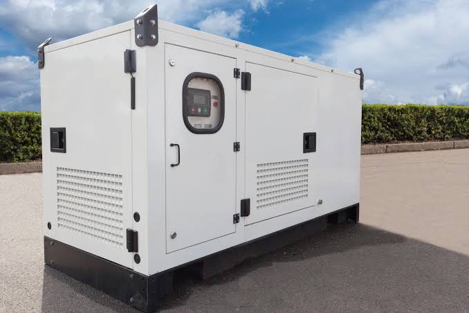
ATS / MTS Kenya
ATS/MTS solutions from Paneltech Systems provide reliable Automatic and Manual Transfer Switches for seamless power transfer in industrial and commercial electrical systems.
View Product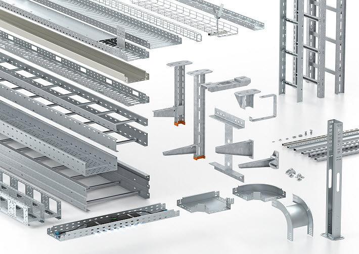
Cable Systems
Paneltech Systems offers comprehensive cable management systems for efficient, secure and organised cable setups across industrial and commercial environments.
View Product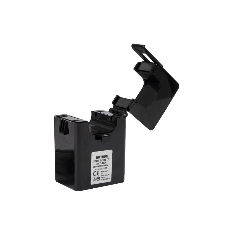
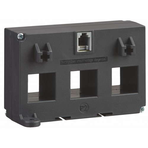
Single Phase RJ12 CT
Single Phase RJ12 current transformer for precise single-phase current measurement in power monitoring and metering applications.
View Product
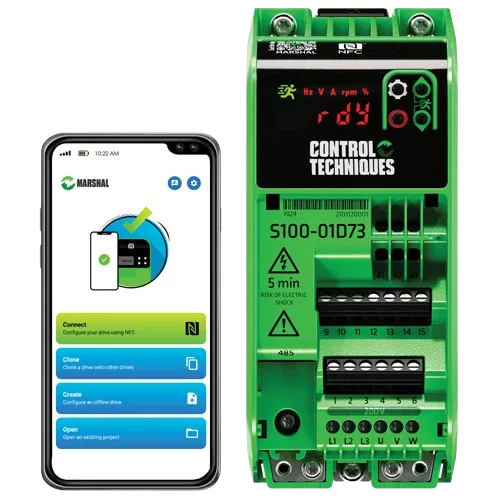
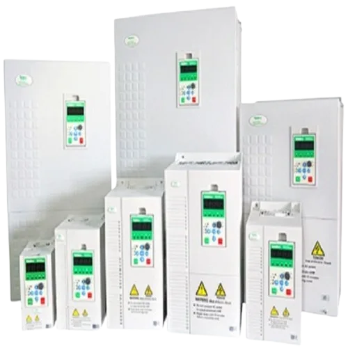
Commander C
Commander C VFD Drives from Paneltech Systems provide advanced motor control for industrial and commercial applications. Enhance efficiency and reliability.
View ProductUnderstanding single line diagram Kenya projects depend on helps engineers, consultants, contractors, and facility managers verify that the proposed electrical system is safe, compliant, and capable of meeting both present and future operational demands.
In Kenya, reviewing an SLD is particularly important because electrical systems often include:
- KPLC utility supplies
- Diesel standby generators
- Solar PV systems
- Battery Energy Storage Systems (BESS)
- Automatic Transfer Switches (ATS)
- APFC panels
- Variable Frequency Drives (VFDs)
- Energy monitoring systems
At Paneltech Systems Ltd, we prepare, review, and manufacture switchboards directly from approved Single Line Diagrams, ensuring every panel complies with recognised engineering standards and project requirements. Learn more about our engineering expertise at about, explore our products at products, or contact our engineering team through contact.
A Single Line Diagram (SLD) is a simplified drawing that represents an electrical power distribution system using single lines and standard electrical symbols. It shows how electrical power flows from the incoming supply to transformers, switchboards, distribution boards, generators, loads, and protective devices.
Instead of showing every conductor individually, an SLD presents the overall electrical architecture in a clear, simplified format.
Typical components include:
- Utility incomers
- Transformers
- Main switchboards
- Busbars
- Circuit breakers
- Distribution boards
- Generators
- Solar systems
- Battery storage
- Earthing arrangements
A properly prepared Single Line Diagram allows engineers to verify protection, coordination, equipment ratings, and future expansion before manufacturing begins. Correcting mistakes on paper is significantly easier and less expensive than modifying completed switchboards.
An approved SLD supports:
- Safe system design
- Faster project delivery
- Accurate equipment selection
- Regulatory compliance
- Easier maintenance
Every major electrical installation should have an up-to-date SLD.
Before approving a Single Line Diagram, verify the incoming supply arrangement, transformer ratings, switchboard fault levels, protective device ratings, cable sizes, earthing method, interlocking logic, and provisions for future expansion. The SLD should accurately represent how the completed electrical installation will operate under both normal and fault conditions.
Key items include:
- Utility incomer
- Main breaker ratings
- Busbar current rating
- Fault level
- ATS arrangement
- Generator integration
- Earthing system
- Protection coordination
An SLD should contain all critical design information needed to manufacture, install, test, and commission the electrical system safely.
| Specification | Typical Requirement |
|---|---|
| System Voltage | 415V AC |
| Frequency | 50 Hz |
| Incoming Supply | KPLC / Generator / Solar |
| Busbar Rating | Project Specific |
| Fault Rating | 25kA–65kA (Project Dependent) |
| Earthing System | TN-S / TN-C-S / TT |
| Protection Devices | MCCB / ACB / MCB |
| Metering | Multifunction Energy Meter |
| Standards | IEC 61439 / IEC 60364 |
| Drawing Format | Single Line Diagram (SLD) |
The SLD should clearly identify the source of electrical power and how it enters the installation. This information determines switchboard ratings, protection settings, and system configuration.
Common incoming supplies include:
- KPLC utility supply
- Diesel generators
- Solar PV systems
- Battery Energy Storage Systems
- Dual utility incomers
Every source should be clearly labelled and rated.
Every protective device shown on the SLD should include its current rating, interrupting capacity, and protective function. These values ensure the switchboard can safely withstand expected operating and fault conditions.
Typical information includes:
- Current rating (A)
- Breaking capacity (kA)
- Trip characteristics
- Protection settings
- Device type
Incorrect breaker selection can compromise system safety.
The busbar system distributes power throughout the switchboard and must be correctly sized for continuous current, future expansion, and prospective fault levels.
Busbar information typically includes:
- Material
- Current rating
- Fault withstand rating
- Arrangement
- Segregation
Paneltech designs LV switchboards with engineered busbar systems through low-voltage-panels.
Where standby generators are installed, the SLD should clearly show Automatic Transfer Switch (ATS) arrangements and electrical or mechanical interlocking that prevents unsafe parallel operation unless specifically designed.
Typical ATS information includes:
- Utility incomer
- Generator incomer
- ATS operation
- Manual bypass
- Interlocking method
Proper interlocking improves operational safety.
Modern SLDs increasingly include renewable energy systems alongside traditional utility supplies. These connections should be clearly shown to ensure safe operation and protection coordination.
Common renewable energy components include:
- Solar inverters
- Battery storage
- Hybrid inverters
- AC combiner panels
- DC isolation
Paneltech also designs solar-ready distribution panels through #solar-ac-db-combiner.
The earthing arrangement shown on the SLD is essential for personnel safety and fault protection. Every switchboard should clearly indicate the earthing system used throughout the installation.
Common earthing systems include:
- TN-S
- TN-C-S
- TT
The SLD should also identify:
- Earth bars
- Protective conductors
- Bonding arrangements
Protection coordination ensures that only the device closest to a fault disconnects, minimising disruption to the remainder of the electrical installation.
An SLD should support:
- Selective coordination
- Discrimination studies
- Time-current analysis
- Protective relay settings
Proper coordination improves system uptime.
A well-designed Single Line Diagram should accommodate future electrical growth without requiring complete replacement of the switchboard.
Future provisions may include:
- Spare feeders
- Larger busbars
- Additional generators
- Solar expansion
- Battery storage
- Extra metering
Planning ahead reduces future upgrade costs.
Switchboards represented on the SLD should also be specified with enclosure ratings appropriate for their installation environment.
Nairobi
Typical applications:
- Commercial buildings
- Office developments
- Mixed electrical loads
Coastal Kenya
Typical requirements:
- IP65 enclosures
- Corrosion-resistant construction
Industrial Areas
Typical requirements:
- Dust protection
- Heavy-duty switchboards
- High fault ratings
Environmental conditions should influence final panel specifications.
Many project delays and manufacturing changes result from incomplete or poorly reviewed Single Line Diagrams. Careful engineering review reduces these risks before fabrication begins.
Common mistakes include:
- Missing fault ratings
- Incorrect breaker sizes
- No generator contribution
- No future spare capacity
- Missing metering
- Incorrect earthing details
- No protection coordination
Professional review ensures the drawing accurately reflects project requirements.
Single Line Diagrams should support electrical systems designed in accordance with recognised international standards and Kenyan regulatory requirements.
Relevant standards include:
- IEC 61439 – Low Voltage Switchgear Assemblies
- IEC 60364 – Electrical Installations
- IEC 60947 – Low Voltage Switchgear and Controlgear
- BS EN standards for switchgear
- EPRA electrical requirements applicable in Kenya
Paneltech Systems Ltd reviews Single Line Diagrams before manufacturing to ensure switchboards meet project specifications, operational requirements, and recognised engineering standards.
Our specialised services include:
- Low Voltage Switchboards
- Single Line Diagram Review
- Motor Control Centres (MCCs)
- APFC Panels
- ATS / MTS Systems
- VFD Control Panels
- Energy Monitoring Panels
- PLC Automation Panels
- Electrical Engineering Consultation
- Custom Panel Manufacturing
Explore our engineering solutions through home-main, access technical resources through knowledge-site, discover residential solutions through paneltechhomes, or visit home1.
Understanding a Single Line Diagram helps ensure electrical systems are correctly designed before manufacturing begins.
What is a Single Line Diagram?
It is a simplified drawing showing how electrical power flows through an installation using standard electrical symbols and single-line representations.
Why is an SLD important?
It forms the basis for switchboard design, equipment selection, protection coordination, and system installation.
Who should approve an SLD?
Qualified electrical engineers, consultants, and project stakeholders should review and approve the drawing before manufacturing begins.
Does an SLD include solar and generators?
Yes. Modern Single Line Diagrams typically include utility supplies, generators, solar PV systems, battery storage, and transfer systems where applicable.
Can Paneltech review an existing Single Line Diagram?
Yes. Paneltech engineers review SLDs to verify equipment ratings, fault levels, protection coordination, and overall switchboard suitability before fabrication.
Powering Kenya's Future with Reliable Electrical Solutions
Email: [email protected]
Phone: 0799 531765
Location: Nairobi, Kenya
Website: https://paneltechsystems.co.ke/
Our Specialized Services:
- Low Voltage (LV) Panels & APFC Panels
- VFD Drive Solutions & ATS / MTS Systems
- Solar Power & EV Charging Infrastructure
- Electrical Supplies & Engineering Consultations