Lightning Protection Kenya: IEC 62305 Design for Buildings
A properly designed lightning protection system helps protect buildings, people and electrical infrastructure from the effects of lightning strikes. This guide explains IEC 62305 risk assessment, air terminals, down conductors, earth termination systems and how lightning protection .
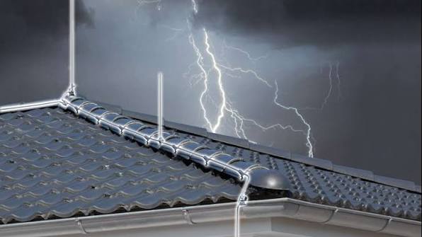
Lightning is a serious electrical and structural hazard for buildings, industrial facilities, communication sites, farms, hospitals, commercial premises, and other structures exposed to thunderstorms. A direct strike can cause fire, structural damage, equipment destruction, and dangerous voltage differences within a building.
A properly engineered lightning protection Kenya solution provides a controlled path for lightning current to travel from the point of interception to earth while reducing the risk of dangerous side flashes and voltage differences.
However, a lightning protection system is more than installing a metal rod on the roof. Effective protection requires risk assessment, air-termination design, down conductors, equipotential bonding, earth termination, separation distances, and appropriate surge protection.
The IEC 62305 series provides an internationally recognized framework for lightning protection design, risk management, and protection measures. The actual system should be designed and installed by competent professionals according to the applicable standards, project requirements, and local regulatory requirements.
Paneltech Systems Ltd. provides electrical engineering and protection solutions for industrial, commercial, and infrastructure projects across Kenya. Explore our electrical products and solutions or learn more about our engineering capabilities through the Paneltech Systems About page.
What Is a Lightning Protection System?
A lightning protection system (LPS) is an engineered network designed to intercept lightning, conduct the current safely toward earth, and disperse it through an earth-termination system. It also incorporates measures to reduce dangerous potential differences and protect internal electrical systems.
An external lightning protection system generally consists of three major elements:
- Air-termination system
- Down-conductor system
- Earth-termination system
An internal lightning protection system may additionally require:
- Equipotential bonding
- Surge Protective Devices (SPDs)
- Separation distances
- Shielding
- Coordinated earthing and bonding
The purpose is not necessarily to prevent lightning from striking a structure.
Instead, the system provides a controlled route for the lightning current if the structure is struck.
This distinction is important.
A properly designed LPS helps reduce the probability of uncontrolled current travelling through:
- Building steelwork
- Electrical cables
- Plumbing
- Communication systems
- Structural components
- Flammable materials
The system must therefore be considered as part of the building's overall electrical safety strategy.
What Is IEC 62305?
IEC 62305 is a series of international standards covering protection against lightning, including general principles, risk management, physical damage protection, and protection of electrical and electronic systems. It provides the engineering framework used to design and assess lightning protection systems.
IEC 62305 is divided into several parts addressing different aspects of lightning protection.
The series includes:
- IEC 62305-1: General principles
- IEC 62305-2: Risk management
- IEC 62305-3: Physical damage to structures and life hazard
- IEC 62305-4: Electrical and electronic systems within structures
This structure is important because lightning protection is not simply a question of choosing a lightning rod.
The design process considers:
- Characteristics of the structure
- Location
- Occupancy
- Contents
- Consequences of damage
- Lightning exposure
- Electrical systems
- Communication systems
- Fire risk
- Required protection level
For a professional IEC 62305 design, the engineer should therefore begin with the risk assessment rather than immediately selecting physical components.
Why Lightning Risk Assessment Comes First
A lightning risk assessment determines whether protection is required and helps establish the appropriate protection measures for the structure. It considers lightning exposure, building characteristics, occupants, services, and potential consequences of a lightning event.
Not every structure has the same lightning risk.
A small residential structure and a large industrial facility may have very different consequences if struck.
A risk assessment can consider factors such as:
- Structure dimensions
- Location
- Number of occupants
- Construction materials
- Connected utility services
- Fire risk
- Critical equipment
- Business interruption
- Environmental consequences
For example, a manufacturing plant may have significant financial exposure because a lightning event could damage electrical infrastructure and stop production.
A hospital may have additional concerns because critical medical equipment and life-support systems depend on reliable electrical infrastructure.
A telecommunications facility may require protection of both the physical structure and sensitive electronic equipment.
The risk assessment therefore helps determine the appropriate protection strategy rather than applying an identical system to every building.
Lightning Protection Levels
IEC 62305 uses Lightning Protection Levels (LPLs) to represent different levels of protection performance required by a lightning protection system. The selected level influences design parameters such as the interception system and spacing of down conductors.
The IEC 62305 framework recognizes four Lightning Protection Levels:
- LPL I
- LPL II
- LPL III
- LPL IV
LPL I represents the most stringent protection level, while LPL IV represents the least stringent within the classification system.
The required level depends on the outcome of the risk assessment.
The protection level can influence:
- Rolling-sphere design parameters
- Mesh dimensions
- Down-conductor spacing
- Lightning current assumptions
- Separation requirements
The engineer should therefore avoid selecting an LPL simply because it is commonly used for a particular building type.
The appropriate classification should follow the risk-management process and applicable project requirements.
Air-Termination Systems
The air-termination system is the part of the LPS intended to intercept lightning strikes and provide a controlled connection to the down-conductor network. It may use rods, conductors, meshes, or combinations depending on the structure and design method.
Air terminals are often what people refer to as a "lightning rod."
However, modern LPS design can involve more than a single vertical rod.
Possible components include:
- Air rods
- Roof conductors
- Horizontal conductors
- Roof meshes
- Natural structural components where appropriate
The arrangement depends on:
- Building geometry
- Roof configuration
- Protection level
- Design method
- Presence of rooftop equipment
- Structural materials
The three commonly referenced design methods include:
Rolling Sphere Method
An imaginary sphere is effectively rolled over the structure.
Areas touched by the sphere represent locations potentially exposed to direct lightning attachment.
The method is particularly useful for complex structures.
Protective Angle Method
A protected zone is established based on the geometry and height of the air-termination component.
The method has limitations and must be applied within its applicable design conditions.
Mesh Method
A conductive mesh is arranged across the roof according to the applicable protection requirements.
This approach can be useful for large roof areas.
Lightning Down Conductors
Down conductors provide the intentional path for lightning current between the air-termination system and the earth-termination system. They should be arranged to provide suitable current paths while minimizing dangerous side-flashing and inductive effects.
The down-conductor system is a critical part of the LPS.
A poorly designed down-conductor arrangement can create high voltage differences and unwanted current paths.
Design considerations include:
- Number of down conductors
- Spacing
- Routing
- Conductor material
- Mechanical protection
- Connections
- Bends
- Separation from internal services
Where practical, down conductors should follow direct routes with minimized unnecessary bends.
Lightning current contains high-frequency components, meaning conductor geometry matters.
Sharp bends and poorly planned routing can increase inductive effects.
The design should also consider the relationship between down conductors and:
- Electrical wiring
- Metal pipework
- Reinforcement
- Communication cables
- HVAC systems
- Building services
Earth-Termination System
The earth-termination system disperses lightning current into the ground and works together with the down-conductor network to complete the lightning-current path. Its design must consider soil conditions, electrode arrangement, bonding, and the overall earthing system.
A lightning protection system does not end when the down conductor reaches ground level.
The lightning current must be safely dispersed into the earth.
Possible earth-termination arrangements include:
- Ring electrodes
- Earth rods
- Foundation earth electrodes
- Radial conductors
- Combined electrode arrangements
The most appropriate solution depends on:
- Soil resistivity
- Building structure
- Site geometry
- Existing earthing system
- Lightning protection design
- Electrical installation requirements
Soil conditions vary considerably across Kenya.
A solution that performs well in one location may not be appropriate for another.
For this reason, the earth-termination system should be engineered based on actual site conditions rather than relying solely on a standard number of earth rods.
Lightning Protection vs Surge Protection
A lightning protection system primarily manages the physical effects and current path of a lightning strike, while Surge Protective Devices protect electrical and electronic systems against transient overvoltages. A comprehensive protection strategy may require both.
This distinction is frequently misunderstood.
An external LPS can provide a controlled route for lightning current.
However, a lightning event can still generate:
- Conducted surges
- Induced voltages
- Electromagnetic fields
- Transient overvoltages
These can damage:
- PLCs
- Computers
- CCTV systems
- Fire alarms
- Control systems
- VFDs
- Power supplies
- Communication equipment
- Electronic meters
SPDs help limit transient overvoltages and divert surge energy away from sensitive equipment.
A coordinated system may therefore include:
External LPS + Earthing/Bonding + Coordinated SPDs
Paneltech Systems also works with LV electrical panel systems where surge protection can be incorporated into appropriately designed distribution equipment.
Where Should Surge Protective Devices Be Installed?
SPDs are normally installed at appropriate points within the electrical distribution system to limit transient overvoltages. Protection should be coordinated across incoming supplies, distribution boards, and sensitive equipment according to the installation design.
The exact SPD arrangement depends on the building and electrical system.
Potential locations include:
- Main incoming switchboard
- Main distribution boards
- Sub-distribution boards
- Sensitive equipment panels
- Data and communication interfaces
- Solar PV systems
- Control panels
A coordinated SPD system should consider:
- Type of electrical supply
- Earthing arrangement
- Expected surge environment
- Equipment sensitivity
- SPD voltage rating
- Short-circuit conditions
- Backup protection
- Lead length
Poorly installed SPDs may provide less protection than expected.
Correct conductor routing and connection length are particularly important because transient currents can have very fast rise times.
Lightning Protection for Industrial Buildings
Industrial facilities often require integrated lightning protection because they combine large structures, electrical distribution systems, control electronics, metallic services, and expensive production equipment. Protection should address both physical lightning effects and electrical transients.
Industrial buildings may contain:
- LV switchboards
- MCCs
- Transformers
- Generators
- VFD systems
- PLCs
- SCADA systems
- Solar installations
- Communication networks
- Process-control equipment
A lightning event can therefore affect multiple systems simultaneously.
A properly coordinated design should consider the relationship between the building LPS and internal electrical infrastructure.
For example:
Lightning strike → LPS → Down conductors → Earth system
while separately:
Lightning transient → Electrical network → SPD → Protected equipment
The two protection strategies work together.
Paneltech Systems provides VFD drive solutions and industrial control infrastructure where sensitive automation equipment may require coordinated surge protection.
Lightning Protection for Solar PV Systems
Solar PV installations require lightning and surge protection considerations because rooftop panels, DC cabling, inverters, and AC distribution can provide pathways for transient energy. The PV protection strategy should be coordinated with the building's overall LPS and earthing design.
Solar installations can introduce additional conductors between the roof and electrical equipment.
Design considerations may include:
- PV module arrangement
- DC cabling
- Inverter location
- AC distribution
- DC SPDs
- AC SPDs
- Earthing and bonding
- Separation distance
- Existing building LPS
The PV system should not be treated as an isolated electrical installation when designing lightning protection for a building.
Paneltech Systems also provides solar AC/DC combiner solutions that can form part of an appropriately engineered solar electrical system.
Separation Distance in Lightning Protection
Separation distance is used to reduce the risk of dangerous sparking between the lightning protection system and nearby conductive or electrical components. The required distance depends on the lightning protection design and relevant parameters specified by the applicable standard.
Lightning current can create significant potential differences.
If an LPS conductor is installed too close to:
- Electrical cables
- Metal pipework
- Communication systems
- Equipment
- Structural components
a side flash may occur.
The solution is not simply to increase physical distance in every case.
Designers may use:
- Appropriate separation
- Equipotential bonding
- Shielding
- Controlled routing
- Suitable SPD arrangements
The calculation should follow the applicable IEC 62305 methodology.
System Specifications Table
A professional lightning protection design should document the risk assessment, protection level, air-termination arrangement, down-conductor network, earth-termination system, bonding, separation distances, and surge protection strategy.
| Parameter | Engineering Consideration |
|---|---|
| Design Standard | IEC 62305 series |
| Risk Assessment | Required to determine protection needs |
| Protection Level | LPL I, II, III or IV as determined by design |
| Air Termination | Rods, conductors, mesh or combination |
| Down Conductors | Multiple paths according to design requirements |
| Earth Termination | Ring, rods, foundation or combined arrangement |
| Bonding | Main electrical and metallic services |
| Separation Distance | Calculated according to LPS design |
| Surge Protection | Coordinated SPDs where required |
| Roof Equipment | PV, HVAC, antennas and metallic structures considered |
| Testing | Continuity, earth system and inspection requirements |
| Documentation | Drawings, calculations, test records and maintenance schedule |
The final specifications should always be based on the actual building, risk assessment, applicable standards, and site conditions.
Testing and Maintenance of Lightning Protection Systems
A lightning protection system requires periodic inspection and maintenance to ensure conductors, connections, earth electrodes, bonding, and protective devices remain in good condition. A system that was correctly installed can still deteriorate over time.
Maintenance inspections should look for:
- Corroded conductors
- Loose connections
- Damaged air terminals
- Mechanical damage
- Broken down conductors
- Altered roof structures
- New rooftop equipment
- Damaged earth connections
- SPD status
- Changes to electrical installations
Building modifications can also affect an existing LPS.
For example, installing:
- Solar panels
- HVAC units
- Antennas
- Water tanks
- New roof structures
may change the original lightning exposure and separation distances.
The LPS should therefore be reassessed whenever major structural or electrical modifications are made.
Contact Paneltech Systems Ltd.
Powering Kenya's Future with Reliable Electrical Solutions
A properly designed lightning protection system can help protect buildings, electrical infrastructure, electronic equipment, and occupants from the consequences of lightning events. Paneltech Systems Ltd. provides electrical engineering solutions for commercial, industrial, and infrastructure projects across Kenya and East Africa.
Our Specialized Services
- Low Voltage (LV) Panels & APFC Panels
- VFD Drive Solutions & ATS / MTS Systems
- Solar Power & EV Charging Infrastructure
- Electrical Supplies & Engineering Consultations
Email: [email protected]
Phone: 0799 531765
Location: Nairobi, Kenya
Website: Paneltech Systems Ltd.
For a lightning protection or electrical infrastructure project, contact our engineering team through the Paneltech Systems Contact page.
You can also explore the Paneltech Systems Knowledge Centre for additional technical information on electrical engineering, protection, automation, and power distribution.