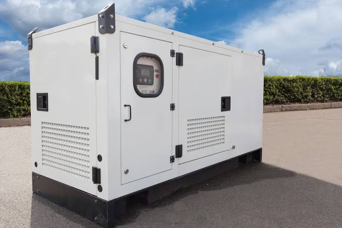
Panel Schedule Template and Load Schedule Template Kenya
Download practical panel and load schedule templates for electrical consultants and contractors. The templates help organise circuits, connected loads, demand factors, breaker ratings, cable sizes and distribution-board information for Kenyan projects.
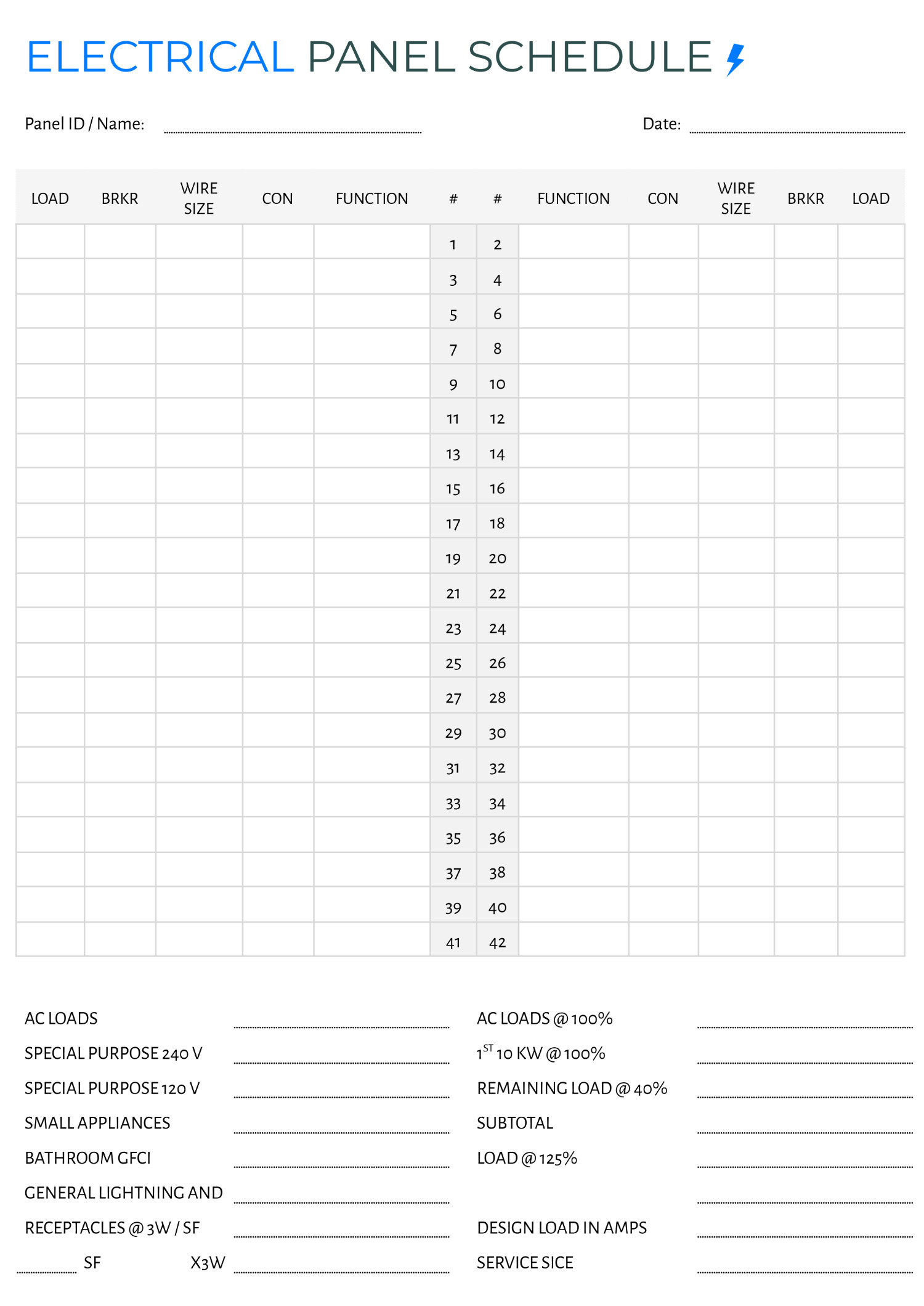
A panel schedule records the circuits, protective devices and connected loads supplied from an electrical panel, while a load schedule summarises the electrical demand of the installation. Using structured templates helps consultants and contractors organise design information, size equipment correctly and coordinate LV panels before procurement.
For electrical projects, accurate schedules are essential before specifying switchboards, distribution boards, cables, generators, transformers or other equipment.
Related Products

LV Panel
High-quality low voltage panels designed for reliable power distribution and protection in industrial and commercial installations.
View Product
Protection Panels
Robust protection panels safeguarding electrical systems and equipment from faults, overloads and short circuits.
View Product
Starter Panels
Motor starter panels for safe starting and stopping of industrial motors with overload and short circuit protection.
View Product
ATS / MTS Kenya
ATS/MTS solutions from Paneltech Systems provide reliable Automatic and Manual Transfer Switches for seamless power transfer in industrial and commercial electrical systems.
View ProductA well-prepared panel schedule template provides a clear record of what each circuit is supplying. A load schedule template Kenya projects can use should additionally capture connected load, demand factors, calculated demand, phase allocation and other information needed for electrical design.
Paneltech Systems Ltd. supports electrical panel manufacturing and engineering solutions for commercial, industrial and infrastructure projects. View the company's electrical products and solutions for more information.
What Is a Panel Schedule?
A panel schedule is a structured table showing the circuits connected to a particular distribution board or electrical panel. It typically identifies circuit numbers, loads, breaker ratings, cable information, phases and spare capacity.
A panel schedule allows the electrical team to understand what is connected to a specific panel without having to trace every circuit physically.
Typical information includes:
- Panel reference
- Circuit number
- Circuit description
- Load type
- Connected load
- Number of phases
- Breaker rating
- Cable size
- Earth conductor
- Circuit length
- Phase allocation
- Demand factor
- Remarks
For larger installations, the schedule can also include:
- Motor ratings
- Starting method
- VFD information
- Emergency loads
- Generator-backed circuits
- UPS-backed circuits
- Spare ways
What Is a Load Schedule?
A load schedule summarises the electrical loads connected to a building, plant or facility and calculates the expected demand. It provides important input for sizing transformers, generators, switchboards, cables and protective equipment.
The load schedule usually begins with connected load.
For example:
| Load | Quantity | Unit Rating | Connected Load |
|---|---|---|---|
| Lighting | 20 | 20 W | 400 W |
| Socket outlets | 10 | 200 W | 2,000 W |
| Pumps | 2 | 5.5 kW | 11 kW |
| HVAC | 3 | 3 kW | 9 kW |
The schedule can then apply appropriate demand or diversity factors to estimate the expected operating demand.
Why Use a Panel Schedule Template?
A panel schedule template standardises how electrical circuit information is recorded across a project. This makes design review, tendering, installation, testing and maintenance easier.
Without a standard format, different engineers may record circuit information differently.
One schedule may show:
Circuit 1 – Lighting – 10A
while another may include:
Circuit 1 – Office Lighting – 1.2 kW – 230 V – 10A MCB – 2.5 mm² Cu – L1.
The second format provides significantly more information.
A standard template helps ensure that important information is not omitted.
Panel Schedule Template for Kenyan Projects
A panel schedule for a Kenyan project should capture enough information to coordinate the distribution board with the project's electrical drawings, cable schedule and protective-device requirements. The final format should be adapted to the project's voltage system and design standards.
Recommended Panel Schedule Template
| Circuit | Description | Load Type | Phase | Connected Load | Breaker | Cable | Earth | Remarks |
|---|---|---|---|---|---|---|---|---|
| 1 | Lighting | Lighting | L1 | [kW] | [A] | [mm²] | [mm²] | |
| 2 | Socket outlets | General power | L2 | [kW] | [A] | [mm²] | [mm²] | |
| 3 | Pump | Motor | L3 | [kW] | [A] | [mm²] | [mm²] | |
| 4 | HVAC | Mechanical | L1 | [kW] | [A] | [mm²] | [mm²] | |
| 5 | Spare | Spare | L2 | — | — | — | — | Future use |
This can be expanded for larger distribution boards.
Load Schedule Template Kenya
A load schedule template Kenya electrical projects can use should record connected loads and calculated demand while allowing the engineer to apply appropriate demand and diversity factors. It should also identify phase loading for balanced three-phase systems.
A useful template can contain:
| Load Category | Quantity | Unit Load | Connected Load | Demand Factor | Maximum Demand |
|---|---|---|---|---|---|
| Lighting | [ ] | [kW] | [kW] | [ ] | [kW] |
| Socket outlets | [ ] | [kW] | [kW] | [ ] | [kW] |
| HVAC | [ ] | [kW] | [kW] | [ ] | [kW] |
| Motors | [ ] | [kW] | [kW] | [ ] | [kW] |
| Pumps | [ ] | [kW] | [kW] | [ ] | [kW] |
| Kitchen equipment | [ ] | [kW] | [kW] | [ ] | [kW] |
| Other loads | [ ] | [kW] | [kW] | [ ] | [kW] |
| Total | [kW] | [kW] |
The demand factors should be based on the actual application and applicable design methodology rather than automatically applying one percentage to every load.
Connected Load vs Maximum Demand
Connected load is the total rated capacity of all listed equipment, while maximum demand represents the expected highest simultaneous operating demand. The distinction is important when sizing electrical infrastructure.
For example, a facility may have:
- 20 kW of lighting
- 30 kW of socket loads
- 50 kW of HVAC
- 100 kW of motors
The connected load is:
20 + 30 + 50 + 100 = 200 kW
However, it may not be necessary for all equipment to operate at full rating simultaneously.
The calculated maximum demand may therefore be lower.
The engineer should establish the appropriate demand factors based on:
- Equipment type
- Operating patterns
- Process requirements
- Occupancy
- Diversity
- Manufacturer information
- Applicable design standards
Three-Phase Load Schedule and Phase Balancing
Three-phase installations should distribute single-phase loads as evenly as practical across the available phases. A good load schedule makes phase imbalance visible before installation.
A simple phase allocation table can be used:
| Circuit | Load | Phase | Current |
|---|---|---|---|
| 1 | Lighting | L1 | [A] |
| 2 | Sockets | L2 | [A] |
| 3 | Lighting | L3 | [A] |
| 4 | Sockets | L1 | [A] |
| 5 | Lighting | L2 | [A] |
| 6 | Sockets | L3 | [A] |
The engineer can then total the expected loading on:
- L1
- L2
- L3
Where significant imbalance exists, circuits can be redistributed.
Phase balancing can help improve system performance and reduce unnecessary neutral loading in applicable systems.
Motor Loads in a Load Schedule
Motor loads require more information than simple resistive loads because starting current, power factor, efficiency and starting method can affect electrical-system design. Motor schedules should therefore provide enough information for protection and distribution calculations.
For motors, consider recording:
- Motor name
- Motor rating
- Voltage
- Phase
- Full-load current
- Power factor
- Efficiency
- Starter type
- VFD requirement
- Starting method
- Duty
- Cable size
- Protection
A motor schedule can also identify whether the motor uses:
- Direct-on-line starting
- Star-delta starting
- Soft starter
- VFD
Paneltech Systems provides VFD drive solutions for applications requiring variable-speed motor control.
Panel Schedule for an MCC
An MCC panel schedule should identify every motor feeder, its rating, starter type, protection, control method and automation interface. This information allows the MCC manufacturer to develop the correct feeder configuration.
A typical MCC schedule could look like:
| Feeder | Motor | Rating | Starter | Protection | Control | VFD |
|---|---|---|---|---|---|---|
| M01 | Pump 1 | 15 kW | DOL | MPCB/OL | Local/Auto | No |
| M02 | Pump 2 | 22 kW | VFD | MCCB/OL | PLC | Yes |
| M03 | Fan | 7.5 kW | VFD | MCCB/OL | Auto | Yes |
| M04 | Conveyor | 11 kW | DOL | MPCB/OL | Local | No |
This information can then be coordinated with the motor-control design.
Load Schedule for Generator Sizing
A load schedule provides important information for generator selection, but generator sizing should consider actual operating demand, motor starting requirements, load sequencing and critical-load priorities.
Simply adding every connected load can result in an unnecessarily large generator.
The engineer should identify:
Essential Loads
Examples include:
- Emergency lighting
- Security systems
- Critical pumps
- Fire-related systems
- Selected refrigeration
- IT equipment
Non-Essential Loads
Examples may include:
- General lighting
- Comfort HVAC
- Non-critical sockets
- Non-essential machinery
The generator can then be sized around the required operating and starting conditions.
Load Schedule for Transformer Sizing
Transformer sizing should be based on the calculated demand and the characteristics of the connected loads, while allowing for appropriate future capacity. Motor starting, harmonics and load growth may also need consideration.
A load schedule helps establish:
- Total connected kW
- Maximum demand
- Power factor
- Estimated kVA
- Future expansion
A simplified relationship is:
kVA = kW ÷ Power Factor
For example, a calculated demand of 400 kW at a power factor of 0.8 gives:
400 ÷ 0.8 = 500 kVA
This is an illustrative calculation only; final transformer selection requires engineering assessment.
Load Schedule and APFC Requirements
A load schedule can help identify facilities with substantial inductive loads that may require power-factor correction. APFC sizing should be based on measured or calculated reactive-power requirements rather than simply applying a fixed percentage.
Large motor loads can contribute to reactive power demand.
The design team may therefore need to evaluate:
- Existing power factor
- Target power factor
- Motor loading
- Transformer loading
- Harmonic distortion
- VFD penetration
- Capacitor requirements
Paneltech Systems provides APFC panel solutions for suitable applications.
Panel Schedule and Cable Sizing
The panel schedule provides circuit-load information that feeds into cable-sizing calculations. Cable selection must also consider installation method, ambient conditions, grouping, voltage drop and protective-device coordination.
The schedule can identify:
- Design current
- Cable length
- Cable type
- Number of cores
- Conductor size
- Protective device
- Installation method
For long cable runs, voltage drop can become a significant consideration.
The final cable size should therefore be confirmed using the project's electrical calculations.
Panel Schedule and Breaker Coordination
Protective devices should be coordinated so that faults are cleared appropriately while unnecessary upstream tripping is minimised. The panel schedule should identify breaker ratings and types clearly enough for protection coordination.
Important parameters can include:
- Breaker rating
- Trip settings
- Breaking capacity
- Curve characteristics
- Short-circuit protection
- Overload protection
- Selectivity requirements
For larger LV systems, a protection study may be required.
The panel schedule should remain consistent with the final protection settings.
Panel Schedule for Solar Installations
Solar projects require separate consideration of DC and AC circuits, inverter ratings, string configuration, protection and isolation. The panel schedule should clearly distinguish PV-related circuits from conventional AC distribution.
Solar schedules may include:
- PV string references
- Combiner boxes
- DC isolators
- Inverter outputs
- AC protection
- Surge protection
- Battery systems
- Monitoring circuits
Paneltech Systems provides solar AC/DC combiner solutions for applicable installations.
What Consultants Should Include in a Panel Schedule
Consultants should include enough information for the contractor and panel manufacturer to understand every circuit and the required protection. The schedule should agree with the single-line diagram and electrical drawings.
Recommended information includes:
- Panel reference
- Panel location
- Incoming supply
- Voltage
- Phase arrangement
- Frequency
- Main incomer
- Busbar rating
- Circuit numbers
- Circuit descriptions
- Connected loads
- Demand factors
- Maximum demand
- Breaker ratings
- Cable sizes
- Earth conductor
- Phase allocation
- Spare ways
- Future capacity
- Remarks
Panel Schedule Quality-Control Checklist
Before issuing a panel schedule, the consultant should cross-check circuit information against the single-line diagram, drawings, load calculations and equipment schedules. This catches inconsistencies before procurement and installation.
Use this checklist:
- Panel reference is correct
- Panel location is identified
- Incoming supply is confirmed
- Voltage is confirmed
- Frequency is confirmed
- Main breaker is correctly rated
- Busbar rating is adequate
- Every circuit has a description
- Loads are correctly calculated
- Phase allocation is reviewed
- Breaker ratings are coordinated
- Cable sizes are confirmed
- Earthing is identified
- Spare ways are included
- Future expansion is considered
- Metering requirements are included
- Schedule matches the SLD
Panel and Load Schedule System Specifications
A standard schedule should capture the core electrical parameters needed to move from design calculations to panel procurement. Project-specific ratings must always be inserted from approved engineering calculations.
| Specification | Required Information |
|---|---|
| Panel Type | DB, MCC, MDB, control panel, etc. |
| System Voltage | Project-specific |
| Frequency | Project-specific |
| Phase | Single or three phase |
| Incoming Rating | [A] |
| Busbar Rating | [A] |
| Short-Circuit Rating | [kA] |
| Connected Load | [kW] |
| Maximum Demand | [kW/kVA] |
| Power Factor | [Value] |
| Number of Circuits | [Number] |
| Breaker Ratings | [A] |
| Cable Sizes | [mm²] |
| Earth Conductors | [mm²] |
| IP Rating | Project-specific |
| Metering | As required |
| SPD | As required |
| Spare Capacity | Project-specific |
| Standards | Applicable IEC/BS EN requirements |
Download and Adapt the Template
The panel and load schedule tables in this guide provide a starting structure for consultants and contractors preparing electrical design documentation. The template should be adapted to each project's equipment, standards, load profile and electrical calculations.
A professional template should ideally contain separate worksheets or sections for:
Sheet 1: Panel Schedule
Records individual circuits and protective devices.
Sheet 2: Load Schedule
Calculates connected load, demand and estimated maximum demand.
Sheet 3: Motor Schedule
Records motor ratings, starting methods and protection.
Sheet 4: Cable Schedule
Records cable types, sizes, lengths and installation information.
Sheet 5: Summary
Provides a consolidated view of:
- Total connected load
- Maximum demand
- Estimated kVA
- Power factor
- Phase loading
- Generator requirement
- Transformer requirement
This structure makes the information easier to transfer from design to procurement.
Contact Paneltech Systems Ltd.
Powering Kenya's Future with Reliable Electrical Solutions
Email: [email protected]
Phone: 0799 531765
Location: Nairobi, Kenya
Website: Paneltech Systems Ltd.
Our Specialized Services
- Low Voltage (LV) Panels & APFC Panels
- VFD Drive Solutions & ATS / MTS Systems
- Solar Power & EV Charging Infrastructure
- Electrical Supplies & Engineering Consultations
For support with panel schedule template requirements, LV panel specifications or electrical distribution projects, contact Paneltech Systems to discuss your project requirements.