How to Size a VFD for a 3-Phase Motor: A 6-Step Engineer's Guide
Step-by-step VFD sizing covering motor full-load current, starting torque, duty cycle, ambient derating, harmonics, and cable-length considerations. With worked example.
To size a VFD correctly, match it to the motor's rated current (not its kW), then derate for ambient temperature, altitude, duty cycle, and switching frequency. Most VFD failures in the field come from undersized drives running close to thermal limits, or correctly sized drives with the wrong duty class. This guide walks through the six checks an engineer should make before placing the order.
Step 1 — Identify the motor's full-load current (FLC)
Always start with the motor's nameplate, not its kW rating. Two motors of the same kW from different manufacturers can have FLCs differing by 10–15% depending on efficiency class and slip.
Related Products
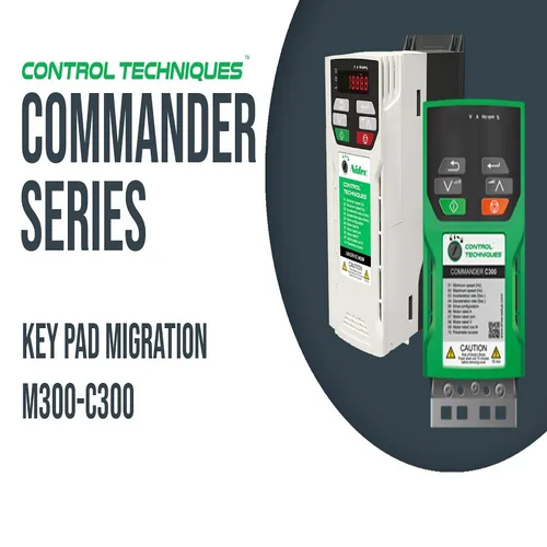
Commander C
Commander C VFD Drives from Paneltech Systems provide advanced motor control for industrial and commercial applications. Enhance efficiency and reliability.
View Product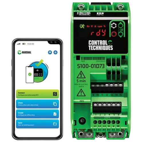
Commander S
Commander S VFD Drives offer energy-efficient motor control for industrial applications. Improve performance and optimise energy usage with reliable Commander S drives.
View Product
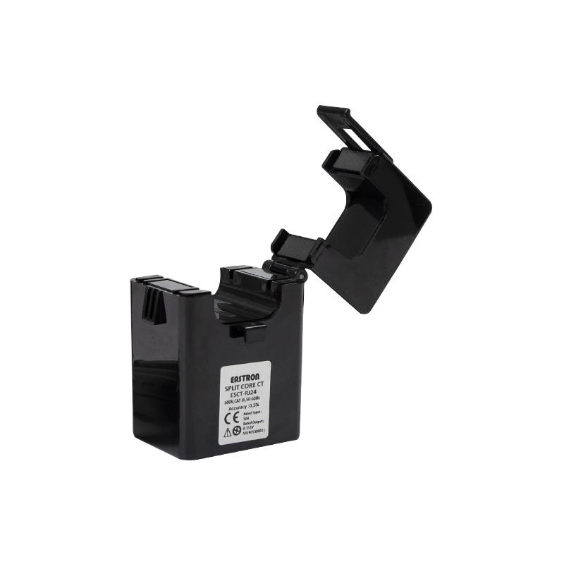
3 Phase Current Transformer
3-Phase Current Transformers for accurate power monitoring and measurement. Paneltech Systems offers high-quality Rishabh 3-Phase CTs for industrial energy monitoring and protection.
View Product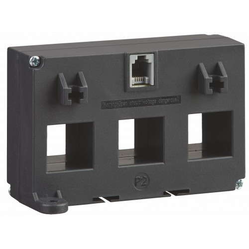
3 Phase RJ12
3-Phase RJ12 from Paneltech Systems for accurate power monitoring and efficient current measurement in industrial applications.
View Product| Motor type | Typical FLC per kW @ 415 V 3-ph (A) |
|---|---|
| IE2 (high efficiency, standard squirrel cage) | 1.8–2.0 A/kW |
| IE3 (premium efficiency) | 1.7–1.9 A/kW |
| IE4 (super-premium / synchronous reluctance) | 1.6–1.8 A/kW |
| Wound-rotor / slip-ring | 2.0–2.5 A/kW (run); higher start |
If you only have kW and no nameplate, use the upper end of these ranges and confirm before ordering.
Step 2 — Match VFD continuous current to motor FLC
The VFD's continuous current rating must be at least 105% of the motor FLC. Most manufacturers publish three current ratings — choose the one that matches your duty:
- Heavy Duty (HD) / Constant Torque (CT) — sized for 150% overload for 60 seconds. Use for conveyors, mixers, positive-displacement pumps, hoists, mills.
- Normal Duty (ND) / Variable Torque (VT) — sized for 110% overload for 60 seconds. Use for centrifugal pumps, fans, blowers, compressors with light starting torque.
- Light Duty (LD) — some manufacturers offer this for fans only, with 110% for 3 seconds. Cheaper but tighter overload window.
A motor controlling a fan at the same kW as one driving a conveyor needs a smaller VFD than the conveyor application — that's the duty-class effect.
Step 3 — Derate for ambient temperature and altitude
Manufacturer ratings are typically for 40°C ambient and altitudes below 1000 m. Both Nairobi-region installations (1600–1800 m elevation) and rooftop / engine-room installations require derating:
- Above 1000 m altitude: derate continuous current by 1% per 100 m
- Above 40°C ambient: derate by 2.5% per °C up to 50°C
- Nairobi (~1700 m) at 40°C = roughly 7% derating from datasheet rating
- Nairobi (~1700 m) at 50°C inside a poorly-ventilated cabinet = roughly 32% derating
If the derated rating drops below the motor FLC, step up to the next VFD frame size.
Step 4 — Account for switching frequency
Higher switching frequency reduces motor noise but increases VFD heat dissipation. Most VFDs are rated at 4 kHz; running at 8 kHz typically requires another 10–15% current derating; 12 kHz requires 20–30%. If the application doesn't need quiet running, stay at the default frequency.
Step 5 — Check cable length and choose filters
Long motor cables cause two problems: voltage reflections that stress motor insulation, and capacitive charging current that adds to the VFD output. Rules of thumb:
- Cables under 30 m: no filter normally required
- 30–100 m: add a dV/dt filter or output reactor
- Over 100 m: use a sine-wave output filter — the motor sees clean sinusoidal voltage
- Submersible motors with screened cables: capacitance per metre is much higher; size the VFD with 15% headroom for capacitive charging current
Step 6 — Address grid-side harmonics
VFDs draw current in pulses (typically 6-pulse rectifier) which causes harmonic distortion on the supply. Single-VFD installations rarely cause problems; plants with multiple VFDs need mitigation:
- Up to 50 kW of total VFD load: 3% line reactors per drive are usually sufficient
- 50–200 kW total VFD load: 5% line reactors or DC link chokes; consider a passive harmonic filter
- Over 200 kW total VFD load: active harmonic filter or 12-pulse / 18-pulse front-end VFDs to stay within IEEE 519 / IEC 61000-3-12 limits
Worked example — borehole pump in Naivasha
| Parameter | Value |
|---|---|
| Motor | 30 kW IE3 submersible pump |
| Nameplate FLC | 57 A @ 415 V |
| Altitude | 1900 m |
| Cabinet ambient (worst case) | 45 °C |
| Cable length to pump | 120 m, screened submersible cable |
| Duty class | Variable Torque (centrifugal pump) |
Sizing calculation:
- VFD continuous current at standard conditions: 57 A × 1.05 = 60 A minimum
- Altitude derating: 1900 − 1000 = 900 m → 9% derating
- Temperature derating: 45 − 40 = 5 °C → 12.5% derating
- Combined derating factor: 1 / (1 − 0.09) × 1 / (1 − 0.125) = 1.26
- Required datasheet rating: 60 A × 1.26 = 75.6 A
- Closest standard frame: 80 A VT-rated drive
- Add 15% for screened-cable capacitive current: 80 × 1.15 = 92 A → step to 100 A frame
- Long-cable filter: sine-wave output filter required (cable > 100 m)
Final selection: 100 A VT-rated VFD with sine-wave output filter.
Common sizing mistakes
- Sizing by motor kW without checking FLC — under-sizes IE2 motors and over-sizes IE4 motors
- Ignoring altitude — a Nairobi installation sized for sea-level datasheet ratings will run hot
- Choosing ND when the application is actually CT — a soft-starting pump suddenly faces a high-inertia load, drive trips on overload
- Forgetting the cabinet ambient — VFD sits in a sealed enclosure at 55°C even when the room is 30°C
- Not accounting for cable charging current on submersibles — VFD reads phantom load that isn't actually shaft torque
Bottom line
Right-sizing a VFD takes minutes once you have the motor nameplate. Two derating factors (altitude + ambient) cover most field installations in Kenya; one cable-length check addresses long-cable applications; one duty-class decision matches the drive to the load profile. The cost difference between a 60 A drive and a 100 A drive is small compared to the cost of replacing the smaller one when it trips out under load.
See our VFD solutions for sizing assistance, panel design, and on-site commissioning across Kenya and East Africa.