Surge Protection Coordination Kenya: Type 1, 2 and 3 SPDs Explained
Surge protection coordination ensures Type 1, Type 2 and Type 3 SPDs work together instead of relying on a single device to protect an entire electrical installation. This guide explains where each SPD belongs, how protection stages are coordinated
Surge protection coordination is essential when an electrical installation contains sensitive equipment that could be damaged by lightning-induced surges, switching transients, or other temporary overvoltage events. Installing an SPD at only one point does not necessarily provide comprehensive protection throughout a building.
A properly coordinated system uses different stages of protection to progressively limit surge energy as it moves from the incoming electrical supply toward sensitive loads.
For many Kenyan commercial, industrial, institutional, and residential installations, this can mean combining Type 1, Type 2, and Type 3 Surge Protective Devices (SPDs), with the selection and arrangement determined by the electrical system, lightning exposure, equipment sensitivity, and applicable standards.
Paneltech Systems Ltd. provides electrical engineering, power distribution, protection, panel, automation, and renewable-energy solutions for projects across Kenya and East Africa. Explore our electrical products and solutions or learn more about the company through the Paneltech Systems About page.
What Is Surge Protection Coordination?
Surge protection coordination means selecting and arranging multiple SPDs so that they work together to limit transient overvoltages at different points in an electrical installation. The objective is to prevent excessive surge energy from reaching downstream equipment while ensuring the protection stages operate appropriately.
An electrical installation can contain equipment with very different levels of surge sensitivity.
For example:
- Main switchboards may tolerate substantial transient energy.
- Distribution boards require additional protection.
- PLCs and control systems may be significantly more sensitive.
- Computers and electronic instruments can require protection close to the equipment.
A coordinated SPD system creates multiple layers.
A simplified arrangement is:
Incoming supply → Type 1 SPD → Type 2 SPD → Type 3 SPD → Sensitive equipment
This does not mean every installation requires all three types.
The appropriate configuration depends on the electrical installation and the applicable standards.
Coordination also involves more than choosing the correct SPD category. Engineers must consider:
- SPD voltage rating
- System earthing arrangement
- Short-circuit rating
- Discharge current
- Protection level
- Backup overcurrent protection
- Conductor length
- Installation location
- Manufacturer coordination requirements
What Is a Surge Protective Device?
A Surge Protective Device is designed to limit transient overvoltages and divert associated surge current away from protected circuits. SPDs help reduce the voltage stress imposed on electrical and electronic equipment during transient events.
A surge can originate from several sources.
Lightning
A nearby or direct lightning event can produce significant transient energy.
Lightning-related surges can enter an installation through:
- Power lines
- Communication cables
- External metallic services
- Earthing systems
- Inductive coupling
Utility Switching
Switching operations within electrical networks can create transient overvoltages.
These may be associated with:
- Transformer switching
- Capacitor switching
- Motor starting/stopping
- Circuit-breaker operation
- Load switching
Internal Equipment
Large industrial loads can generate switching transients when they are energized or disconnected.
Examples include:
- Motors
- Pumps
- Compressors
- VFD systems
- Transformers
- Welding equipment
An SPD provides a controlled path for transient energy so that the voltage seen by downstream equipment is limited.
Type 1 SPD Explained
Type 1 SPDs are intended for the upstream part of an electrical installation where high-energy surge currents may enter the building, particularly where a lightning protection system or similar exposure makes this appropriate. They are designed to handle significant surge current and are commonly installed near the main incoming supply.
Type 1 protection is associated with high-energy surge conditions.
The device is generally installed at the origin of the electrical installation or another suitable upstream position.
A Type 1 SPD may be considered where:
- The building has an external lightning protection system.
- Overhead incoming services create greater exposure.
- The risk assessment identifies significant lightning-current exposure.
- The installation requires high-energy surge-current handling.
Type 1 SPDs are typically characterized by testing using an impulse current waveform associated with partial lightning current.
The exact selection depends on the installation design and applicable requirements.
A Type 1 device should not automatically be assumed to replace downstream surge protection.
Sensitive equipment located far downstream may still experience residual transient voltage.
Type 2 SPD Explained
Type 2 SPDs are commonly installed in main and sub-distribution boards to provide protection against residual lightning-related surges and switching transients. They form an important middle layer of protection between the incoming supply and downstream equipment.
Type 2 SPDs are widely used in electrical distribution systems.
Typical installation locations include:
- Main LV switchboards
- Distribution boards
- Floor distribution panels
- Industrial control panels
- Secondary electrical panels
A Type 2 SPD can help protect downstream circuits against transient overvoltages that remain after upstream protection.
For an industrial installation, a simplified arrangement could be:
Utility supply → Main LV panel → Distribution board → MCC/control panel → Equipment
Type 2 protection can be positioned at suitable distribution points along this network.
Paneltech Systems provides Low Voltage panel solutions for industrial and commercial electrical distribution systems where coordinated protection can be incorporated into the overall design.
Type 3 SPD Explained
Type 3 SPDs provide localized, downstream protection for sensitive electrical and electronic equipment. They are normally installed close to the equipment they protect and are intended to complement, rather than replace, upstream SPD stages.
Type 3 protection is associated with the final stage of surge protection.
It may be appropriate near sensitive equipment such as:
- Computers
- PLCs
- Control systems
- Electronic instrumentation
- Communication equipment
- Medical electronics
- Building-management systems
The closer the protection is to sensitive equipment, the better the system can control the residual voltage reaching that equipment.
However, Type 3 devices generally have lower surge-energy handling capability than upstream Type 1 or Type 2 devices.
They therefore should not be treated as the primary protection against a large incoming surge.
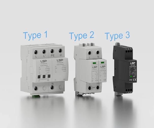
Type 1 vs Type 2 vs Type 3 SPD
Type 1, Type 2 and Type 3 SPDs serve different positions and protection roles within an electrical installation. Type 1 is associated with high-energy upstream surge protection, Type 2 with distribution-level protection, and Type 3 with localized protection of sensitive loads.
| SPD Type | Typical Location | Main Role | Typical Application |
|---|---|---|---|
| Type 1 | Main incoming supply | High-energy surge-current protection | Building with significant lightning exposure |
| Type 2 | Main/sub-distribution boards | Distribution-level surge protection | Commercial and industrial panels |
| Type 3 | Near sensitive equipment | Final-stage protection | PLCs, computers and electronics |
The categories should not be interpreted as a simple quality ranking.
A Type 3 device is not necessarily "better" than a Type 1 device.
Each serves a different role.
The correct system may use one, two, or several protection stages depending on the installation.
Why One SPD May Not Be Enough
A single SPD may not adequately protect every circuit and sensitive device throughout a large installation because cable impedance, distance, equipment sensitivity, and surge energy vary across the electrical network. Multi-stage protection reduces surge stress progressively.
Imagine a large manufacturing facility.
The incoming main panel may be located 100 metres from a PLC control cabinet.
A surge entering the main panel can be reduced by an upstream SPD, but transient voltage can still be influenced by:
- Cable length
- Conductor inductance
- Switching events
- Local surge coupling
Additional protection closer to the PLC can therefore provide another layer of defense.
The same principle applies to:
- Data centres
- Hospitals
- Hotels
- Banks
- Industrial automation plants
- Commercial buildings
The larger and more complex the installation, the more important coordinated protection becomes.
How Type 1, 2 and 3 SPDs Work Together
A coordinated SPD system progressively reduces surge energy and residual voltage as the transient moves toward sensitive loads. Upstream devices handle larger surge currents, while downstream devices provide increasingly localized voltage protection.
A simplified protection hierarchy is:
Stage 1 — Main Incoming Protection
Type 1
The first stage handles high-energy surge conditions where appropriate.
Stage 2 — Distribution Protection
Type 2
The second stage limits residual transient energy at distribution boards.
Stage 3 — Equipment Protection
Type 3
The final stage provides localized protection close to sensitive loads.
The actual coordination must be verified using manufacturer data and the relevant electrical design requirements.
Simply installing three SPDs does not automatically create a coordinated system.
What Is SPD Coordination Distance?
The physical distance and electrical characteristics between SPD stages influence how the devices share surge energy and respond during transient events. Where required, engineers use suitable coordination methods, including manufacturer-approved combinations or appropriate conductor lengths.
SPDs connected too closely together may not necessarily operate as intended if their characteristics are not coordinated.
The coordination can depend on:
- Cable length
- Conductor inductance
- SPD technology
- Manufacturer specifications
- Installation configuration
Some manufacturers specify minimum distances between particular SPD stages.
Where the required distance cannot be achieved, an appropriate coordination device or manufacturer-approved solution may be necessary.
This is one reason SPD selection should be part of the electrical design rather than an afterthought during installation.
SPD Voltage Protection Level
The voltage protection level of an SPD indicates the level of transient voltage that may remain at its terminals under specified test conditions. The selected SPD should have a protection level appropriate for the withstand capability of the equipment being protected.
Sensitive electronic equipment can be damaged by transient voltages even when the electrical supply appears normal.
When selecting an SPD, engineers should consider:
- System nominal voltage
- Maximum continuous operating voltage
- Earthing configuration
- Protection level
- Surge current rating
- Short-circuit capability
- Backup protection
The protection level should be coordinated with the insulation and surge withstand capability of the downstream installation.
Surge Arrester Kenya: Where Should It Be Installed?
A surge arrester or SPD should be installed at a location appropriate to the source and pathway of the transient overvoltage. Main incoming protection, distribution protection, and sensitive-equipment protection may all be required depending on the installation.
In a Kenyan commercial or industrial building, possible locations include:
- Main incoming LV panel
- Generator distribution panel
- Solar AC panel
- Solar DC equipment
- Sub-distribution boards
- MCCs
- Automation panels
- Communication systems
The installation should also account for external services.
A building can be exposed to surges through:
- Utility power
- Generator systems
- Solar PV
- Telecommunications
- Data cables
- CCTV
- External metallic services
Protection should therefore be considered across relevant incoming and outgoing interfaces.
SPD Coordination in Kenyan Electrical Installations
Kenyan installations should account for local lightning exposure, electrical distribution arrangements, building configuration, sensitive equipment, and applicable standards when designing surge protection. A coordinated SPD strategy can help reduce equipment damage caused by lightning-induced and switching transients.
Kenya experiences thunderstorms in many regions, making transient protection an important consideration for electrical infrastructure.
Risk can also vary according to:
- Geographic location
- Building height
- Exposure
- Incoming services
- Electrical network arrangement
- Presence of lightning protection
- Equipment sensitivity
Industrial facilities may have additional exposure from large motors, transformers, generators, and automated systems.
Facilities should therefore avoid choosing an SPD solely because it is advertised as a "surge arrester."
The device must be compatible with the electrical system and properly coordinated with the rest of the installation.
Surge Protection for Solar PV Systems
Solar PV systems may require coordinated AC and DC surge protection because PV arrays, DC cables, inverters, and AC distribution can all be exposed to transient overvoltages. The PV protection system should be coordinated with the building's overall lightning and earthing strategy.
A solar installation can include long DC cable runs between rooftop PV modules and the inverter.
These conductors can be exposed to induced transient voltages.
Protection may therefore include:
- DC SPDs
- AC SPDs
- Appropriate earthing and bonding
- Lightning protection
- Proper cable routing
Paneltech Systems provides solar AC/DC combiner solutions for renewable-energy electrical systems.
The correct SPD configuration should be selected according to the PV system voltage, inverter requirements, system architecture, and applicable standards.
Surge Protection for VFD and Automation Systems
VFDs, PLCs and industrial automation systems can be sensitive to transient overvoltages, making coordinated surge protection particularly important in automated facilities. Protection should be designed around the complete power and control architecture.
Modern factories contain significant amounts of electronic equipment.
Examples include:
- VFDs
- PLCs
- HMIs
- SCADA systems
- Sensors
- Industrial communication equipment
- Electronic meters
A transient entering the facility can potentially affect several interconnected systems.
Paneltech Systems provides VFD drive solutions for applications where motor speed control and energy-efficient operation are required.
Surge protection should be considered alongside:
- Earthing
- Shielding
- Cable routing
- Control-panel design
- Power quality
- Equipment manufacturer's requirements
System Specifications Table
SPD selection should document the electrical system voltage, SPD type, installation position, continuous operating voltage, discharge capability, protection level, backup protection and coordination requirements.
| Parameter | Type 1 SPD | Type 2 SPD | Type 3 SPD |
|---|---|---|---|
| Primary Position | Main incoming supply | Distribution boards | Near sensitive loads |
| Main Purpose | High-energy surge protection | Distribution protection | Final equipment protection |
| Surge Capacity | High | Medium | Lower |
| Typical Use | Lightning-current exposure | LV distribution | Sensitive electronics |
| Installation | Main switchboard | Main/sub-DB | Equipment vicinity |
| Coordination | With downstream SPD | With upstream/downstream devices | With upstream protection |
| Protection Strategy | First stage | Intermediate stage | Final stage |
| Typical Equipment | Main LV infrastructure | Distribution circuits | PLCs, computers, electronics |
These categories are general design concepts. Actual SPD specifications must be selected for the particular electrical installation and verified against manufacturer documentation and applicable standards.
Common SPD Installation Mistakes
Incorrect SPD voltage ratings, poor conductor routing, inadequate backup protection, lack of coordination, and failure to protect all relevant incoming services can reduce the effectiveness of a surge protection system.
Common problems include:
Installing the Wrong Voltage Rating
An SPD must be compatible with the system's nominal voltage and earthing arrangement.
Excessively Long Connection Conductors
Long SPD connections can increase inductive voltage during a fast transient.
The connection should therefore be designed to minimize unnecessary conductor length.
No Upstream Protection
Installing only a small Type 3 device near a computer does not provide the same protection as a properly designed upstream system.
Ignoring Communication Lines
A facility may protect its power supply while leaving Ethernet, telephone, antenna, or other communication interfaces exposed.
No Maintenance
SPDs can deteriorate or operate following surge events.
Status indicators should be inspected where provided, and devices should be replaced according to manufacturer recommendations and condition.
Contact Paneltech Systems Ltd.
Powering Kenya's Future with Reliable Electrical Solutions
A coordinated surge protection system can help protect electrical distribution equipment, automation systems, renewable-energy installations, and sensitive electronics from transient overvoltages.
Paneltech Systems Ltd. provides electrical engineering, LV panel manufacturing, automation, power distribution, solar, and electrical protection solutions for industrial and commercial facilities across Kenya and East Africa.
Our Specialized Services
- Low Voltage (LV) Panels & APFC Panels
- VFD Drive Solutions & ATS / MTS Systems
- Solar Power & EV Charging Infrastructure
- Electrical Supplies & Engineering Consultations
Email: [email protected]
Phone: 0799 531765
Location: Nairobi, Kenya
Website: Paneltech Systems Ltd.
For a tailored electrical protection project, visit the Paneltech Systems Contact page or explore the Paneltech Systems Knowledge Centre for additional engineering resources.