Thermographic Switchgear Surveys Kenya: Finding Faults Before They Trip
A thermographic switchgear survey uses infrared imaging to identify abnormal heat in electrical panels before it develops into equipment failure. Learn how thermal imaging detects loose connections, overloaded circuits and failing components, and how findings are prioritised for maintenance.
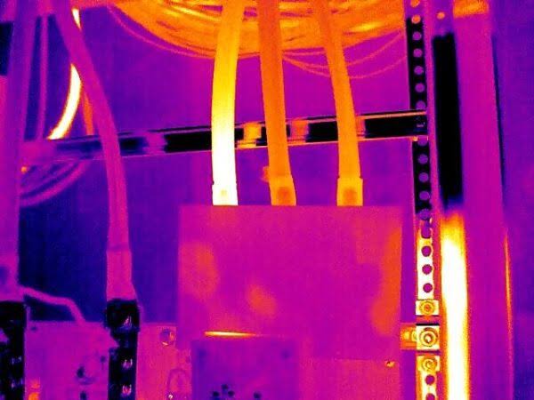
Electrical switchgear can develop dangerous hot spots long before a circuit breaker trips or an obvious equipment failure occurs. Loose connections, overloaded circuits, deteriorating contacts, phase imbalance, and poor terminations can all produce abnormal heat that is invisible during a normal visual inspection.
A thermographic survey Kenya industrial and commercial facilities can use as part of preventive maintenance provides a non-contact method of identifying these temperature abnormalities while equipment remains energised and operating under normal load.
Related Products
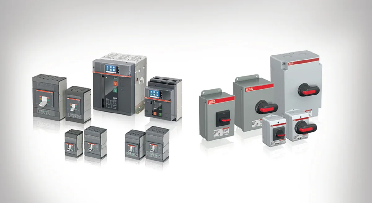
Switchgear Components
A comprehensive range of switchgear components for electrical control and protection in industrial and commercial installations.
View Product
ATS / MTS Kenya
ATS/MTS solutions from Paneltech Systems provide reliable Automatic and Manual Transfer Switches for seamless power transfer in industrial and commercial electrical systems.
View Product
Motor Control
Reliable motor control panels for industrial and commercial use, providing customised solutions for safe and efficient motor operation.
View Product
Protection Panels
Robust protection panels safeguarding electrical systems and equipment from faults, overloads and short circuits.
View ProductFor factories, commercial buildings, hospitals, data facilities, warehouses, water treatment plants, and other facilities with critical electrical infrastructure, thermal imaging can provide an early warning before a small connection problem becomes a shutdown, equipment failure, or electrical safety incident.
Paneltech Systems Ltd. provides electrical engineering, panel, testing, maintenance, and power distribution solutions for industrial and commercial installations across Kenya. Our electrical products and solutions support facilities that require reliable LV distribution, motor control, protection, monitoring, and electrical infrastructure.
What Is a Thermographic Switchgear Survey?
A thermographic switchgear survey uses an infrared camera to detect abnormal temperature patterns in energised electrical equipment. It helps maintenance teams identify potential faults such as loose connections, overloaded circuits, phase imbalance, and deteriorating components before they cause an unexpected shutdown.
Unlike a conventional visual inspection, thermal imaging allows an engineer to see heat patterns that cannot be detected by the naked eye.
An infrared camera measures infrared radiation emitted from surfaces and converts the information into a thermal image. Electrical components operating under load naturally generate some heat, but abnormal temperature differences can indicate developing problems.
A survey may cover:
- Main switchboards
- Motor Control Centres (MCCs)
- Distribution boards
- Automatic Power Factor Correction (APFC) panels
- Circuit breakers
- Busbar connections
- Cable terminations
- Contactors
- Motor starters
- Fuses
- Transformers
- VFD panels
- Generator distribution systems
The objective is not simply to find the hottest component.
A competent thermographer looks for temperature patterns and temperature differences between comparable components.
For example, if three phases feeding a motor are carrying approximately similar currents but one termination is significantly hotter than the other two, the temperature difference may indicate a loose or deteriorating connection.
Facilities using Low Voltage (LV) panels can incorporate thermographic inspection into their wider preventive maintenance programme to identify developing electrical problems before they affect production.
Why Electrical Panels Develop Hot Spots
Electrical hot spots generally occur when resistance, current, or both increase at a particular point in an electrical circuit. Loose connections, overloaded conductors, damaged contacts, poor terminations, and phase imbalance are common causes of abnormal heating.
Electrical heating can be understood using the relationship:
P = I²R
Where:
- P = power dissipated as heat
- I = current
- R = resistance
This relationship is particularly important because heating increases rapidly as current increases.
A small increase in resistance at a poor connection can therefore produce significant localised heating when substantial current flows through the connection.
Common causes include:
Loose Terminations
A loose cable lug or busbar connection creates increased contact resistance.
As current flows through the connection, heat develops at the high-resistance point.
If left uncorrected, the heat can cause:
- Further degradation
- Oxidation
- Insulation damage
- Terminal deterioration
- Increased resistance
- Eventual failure
This can create a self-reinforcing failure cycle.
Overloaded Circuits
A circuit operating above its intended design load generates additional heat.
Thermal imaging can help identify circuits that consistently operate at elevated temperatures, although the thermal image alone does not establish whether a circuit is overloaded.
The thermographic finding should be correlated with:
- Measured current
- Cable size
- Protective-device rating
- Load characteristics
- Ambient temperature
- Installation method
Phase Imbalance
Three-phase systems should operate with appropriately balanced loads.
If one phase carries substantially more current than the others, it may exhibit a higher temperature.
Phase imbalance can occur because of:
- Uneven single-phase loads
- Motor problems
- Loose connections
- Supply abnormalities
- Incorrect circuit distribution
A thermal scan can identify the resulting temperature difference and prompt further electrical testing.
Deteriorating Contacts
Circuit breakers, contactors, isolators, and switching devices contain contacts that can deteriorate over time.
Worn or damaged contacts may create higher resistance and localised heating.
Thermal imaging can therefore provide an early indication that a switching component requires further investigation or replacement.
What Does an Infrared Switchgear Scan Detect?
An infrared switchgear scan detects abnormal thermal patterns associated with electrical connections, conductors, switching devices, and distribution equipment. It does not replace electrical testing, but it provides valuable condition-monitoring information without physically touching energised components.
A properly conducted scan can identify temperature anomalies involving:
- Cable lugs
- Busbar joints
- Breaker terminals
- Fuse holders
- Contactors
- Isolators
- Transformer connections
- Motor feeders
- Neutral connections
- Distribution circuits
Thermal imaging can be particularly valuable where opening or shutting down equipment would interrupt critical operations.
However, an infrared camera does not directly diagnose every electrical problem.
A thermal image should be treated as an indicator requiring engineering interpretation, not as a complete electrical test.
For example, a hot connection may indicate a loose terminal, but the engineer should investigate the underlying electrical and mechanical condition before deciding on corrective action.
Thermographic Survey vs Visual Inspection
Visual inspection and thermographic inspection complement each other rather than replacing one another. Visual checks identify physical defects, while thermal imaging can reveal abnormal heat patterns that may not yet be visible.
A comprehensive maintenance programme should use multiple inspection methods.
| Inspection Method | What It Can Identify |
|---|---|
| Visual inspection | Physical damage, corrosion, loose covers, contamination |
| Thermal imaging | Abnormal temperature patterns and hot spots |
| Current measurement | Load imbalance and excessive current |
| Insulation testing | Insulation deterioration |
| Torque verification | Loose mechanical/electrical connections |
| Power-quality analysis | Voltage, harmonics and imbalance |
| Functional testing | Equipment operation and protection response |
Thermography becomes particularly powerful when combined with other diagnostic information.
For example:
Thermal anomaly + high current + loose connection = strong evidence requiring immediate investigation.
This multi-method approach reduces the risk of making maintenance decisions based on a single measurement.
When Should a Thermographic Survey Be Performed?
Thermographic inspections are most useful when electrical equipment is energised and carrying a meaningful load. Facilities should establish inspection intervals according to equipment criticality, operating conditions, previous findings, and maintenance requirements.
A survey performed on an unloaded panel may fail to reveal developing problems because the electrical current—and therefore heat generation—is too low.
Thermographic surveys are commonly scheduled:
- During planned preventive maintenance
- Before major production periods
- After electrical modifications
- Following repeated nuisance trips
- After equipment overload incidents
- When abnormal smells or discolouration are noticed
- As part of annual electrical inspections
- After major panel upgrades
High-criticality facilities may require more frequent monitoring.
Examples include:
- Manufacturing plants
- Hospitals
- Data centres
- Cold-storage facilities
- Water treatment plants
- Pharmaceutical facilities
- Continuous-process industries
The correct frequency should be determined through a risk-based maintenance programme rather than applying a single interval to every facility.
How Findings Are Prioritised
Thermographic findings should be prioritised according to temperature difference, equipment criticality, load conditions, fault type, and the likelihood of failure. A hot spot on a critical production feeder may require faster action than a similar anomaly on a non-critical circuit.
Not every hot spot represents an emergency.
Thermal findings should be investigated in context.
A practical classification may include:
| Priority | Typical Condition | Recommended Action |
| Critical | Severe abnormal heating or rapidly worsening condition | Immediate investigation/shutdown where safe |
| High | Significant temperature difference at critical equipment | Correct at earliest planned opportunity |
| Medium | Moderate anomaly requiring verification | Monitor and schedule corrective maintenance |
| Low | Minor difference with no other abnormal evidence | Record and monitor |
These categories should not be treated as universal temperature limits.
The acceptable temperature of a component depends on:
- Component type
- Manufacturer specifications
- Ambient temperature
- Load current
- Material
- Connection type
- Enclosure conditions
- Applicable standards
For this reason, a professional thermal survey report should explain the finding rather than simply stating that a component is "hot."
System Specifications Table
A professional thermographic inspection should document the camera, electrical equipment, environmental conditions, load information, thermal findings, and recommended corrective actions. Good documentation allows future surveys to identify whether a condition is improving or deteriorating.
| Parameter | Typical Requirement |
| Inspection Method | Infrared thermography |
| Equipment Condition | Energised and preferably under representative load |
| Inspection Targets | LV panels, MCCs, switchgear, transformers and connections |
| Thermal Camera | Calibrated professional infrared camera |
| Measurement | Surface temperature and temperature differential |
| Electrical Data | Current and voltage where available |
| Environmental Data | Ambient temperature and relevant conditions |
| Documentation | Thermal image + corresponding visual image |
| Reporting | Finding, severity, probable cause and recommendation |
| Follow-Up | Reinspection after corrective action |
| Standards | Applicable IEC/BS EN and manufacturer requirements |
Paneltech Systems can support facilities with broader electrical engineering and panel solutions where thermographic findings indicate that equipment requires modification, replacement, protection upgrades, or improved power distribution.
Thermography in Kenya's Industrial Environment
Kenyan industrial facilities can benefit from thermographic surveys because electrical equipment often operates under demanding load, environmental, and power-quality conditions. Local maintenance programmes should account for dust, humidity, high operating temperatures, production loads, and the consequences of unplanned downtime.
Environmental conditions can influence electrical equipment performance.
In coastal locations such as Mombasa, humidity and salt-laden air can contribute to corrosion of electrical connections and enclosures.
In dusty industrial environments, contamination can accumulate around electrical equipment and reduce heat dissipation.
Thermal imaging can help identify abnormal heating associated with these conditions, but it should form part of a broader maintenance programme that includes:
- Cleaning
- Torque checks
- Insulation testing
- Earthing verification
- Power-quality analysis
- Protection testing
- Component replacement
- Enclosure inspection
Where motor-driven equipment is involved, thermographic findings can also be reviewed alongside the condition of VFD drive systems and motor control equipment.
Contact Paneltech Systems Ltd.
Powering Kenya's Future with Reliable Electrical Solutions
Paneltech Systems Ltd. provides electrical engineering, panel manufacturing, testing, commissioning, maintenance, and power distribution solutions for industrial and commercial facilities in Kenya.
If a thermal scan identifies overheating in a switchboard, MCC, distribution panel, or other electrical equipment, our engineering team can help assess the wider system and recommend appropriate corrective measures.
Our Specialized Services
- Low Voltage (LV) Panels & APFC Panels
- VFD Drive Solutions & ATS / MTS Systems
- Solar Power & EV Charging Infrastructure
- Electrical Supplies & Engineering Consultations
Email: [email protected]
Phone: 0799 531765
Location: Nairobi, Kenya
Website: Paneltech Systems Ltd.
For technical enquiries, visit our Contact Paneltech Systems page or explore our Knowledge Centre for additional electrical engineering information.