VFD Harmonic Distortion: Mitigation Options Compared
VFDs inject 5th, 7th, 11th, and 13th harmonics into the supply. This guide compares line reactors, passive filters, active filters, and multi-pulse drives against IEEE 519 and IEC 61000-3-12 limits.
Variable Frequency Drives use diode-bridge rectifiers that draw non-sinusoidal current from the supply, injecting harmonics — most prominently the 5th, 7th, 11th, and 13th orders. Below about 20% VFD content as a share of total load, harmonics are usually tolerable. Above that threshold, mitigation is required to stay within IEEE 519 (utility-friendly) and IEC 61000-3-12 (equipment-compliance) limits, and to avoid downstream problems: capacitor overheating, neutral-current overload, transformer derating, and intermittent-equipment faults.
Quick comparison
| Method | Current THD after | Cost relative | Panel space | Where it fits |
|---|---|---|---|---|
| Bare drive (no filtering) | ~35–45% | 1.0× | Drive only | Small drives, weak harmonic concern |
| 3% line reactor | ~30% | 1.05–1.15× | +10–20% | Mandatory minimum on most modern drives |
| 5% line reactor | ~25% | 1.1–1.2× | +15–25% | VFD load up to ~30% of total |
| DC link choke (integral) | ~30% | 1.05× | None | Built into many modern drives, similar to line reactor |
| Passive harmonic filter | ~5–8% | 1.3–1.6× | +30–50% | VFD load > 30%, mid-size drives |
| Active harmonic filter (AHF) | < 5% | 1.8–2.5× | Dedicated cabinet | Plant-level mitigation, multiple drives |
| 12-pulse VFD | ~10–15% | 1.5–1.8× | Larger drive | Large drives where AHF is overkill |
| 18-pulse VFD | ~5% | 1.8–2.2× | Larger drive | Critical loads where IEEE 519 is mandated |
| Active front-end VFD (AFE) | < 5% | 1.5–2.0× | Slightly larger drive | Regenerative applications + clean front-end |
Why harmonics matter
The diode-bridge rectifier in a standard VFD draws current in two pulses per phase per cycle, not as a clean sine wave. Fourier analysis decomposes that pulsed current into the fundamental plus odd harmonics: 5th (250 Hz on a 50 Hz system), 7th, 11th, 13th, and so on. Each harmonic flows back into the supply, where it can:
Related Products
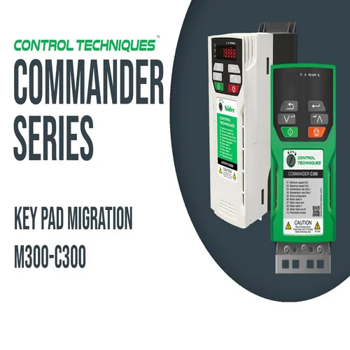
Commander C
Commander C VFD Drives from Paneltech Systems provide advanced motor control for industrial and commercial applications. Enhance efficiency and reliability.
View Product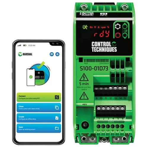
Commander S
Commander S VFD Drives offer energy-efficient motor control for industrial applications. Improve performance and optimise energy usage with reliable Commander S drives.
View Product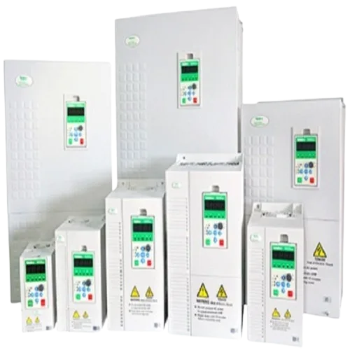
NE-200 Drives
NE-200 Drives offer reliable and efficient performance for industrial applications. Optimise motor speed and energy efficiency with the NE-200 series.
View Product
PFC
Power Factor Correction panels designed to improve power quality and reduce energy costs in industrial installations.
View Product- Overheat capacitor banks — capacitors look low-impedance to harmonics; an APFC stage tuned for 50 Hz gets hammered by 5th and 7th harmonic currents. Capacitor failure within months is the most common consequence of un-mitigated VFD harmonics in Kenyan installations.
- Overheat transformers — eddy losses scale with frequency squared. Transformers feeding heavy VFD loads need K-factor derating.
- Cause neutral current to exceed phase current — triplen harmonics (3rd, 9th, 15th) add in the neutral on three-phase four-wire systems. Standard neutral conductor sizing is insufficient.
- Trip residual current devices — RCDs see harmonic currents as leakage and false-trip.
- Disturb electronic equipment — sensitive instruments, PLC inputs, and computer power supplies can malfunction in high-THD environments.
IEEE 519 vs IEC 61000-3-12
Two standards apply:
- IEEE 519 — sets limits on harmonic voltage and current at the Point of Common Coupling (PCC), the boundary between the utility and the customer's installation. The customer must keep current THD below a percentage that depends on the short-circuit ratio at the PCC.
- IEC 61000-3-12 — sets per-equipment harmonic emission limits. Used by manufacturers to certify their equipment for connection to public LV networks.
KPLC doesn't enforce IEEE 519 with the rigour US utilities do, but consulting engineers increasingly include IEEE 519 compliance in their terms of reference for industrial projects. For projects connecting to weak supply lines, mitigating harmonics is also self-protective — it stops the customer's own capacitor banks and transformers from failing.
The mitigation ladder
Step 1: line reactors (3% or 5%)
A reactor in series with each drive's incoming line. Inductive impedance limits the di/dt of the rectifier current pulse, reducing harmonics. A 3% reactor (the typical minimum) reduces total current THD from ~40% to ~30%. Modern VFDs from ABB, Schneider, Siemens, and Control Techniques often include built-in DC link chokes that have a similar effect.
Use when: VFD load is small (< 20% of installation), or as a baseline mitigation on every drive regardless of size.
Step 2: passive harmonic filters
An LC filter tuned to absorb the 5th harmonic (typical) or a broader tuned filter spanning 5th and 7th. Reduces total current THD to 5–8% — within IEEE 519 limits for most installations.
Use when: VFD load is 30–60% of installation, single drives 30–200 kW. Passive filters are tuned to specific drive ratings, so multi-drive applications need careful design.
Step 3: active harmonic filters (AHF)
A power-electronic device that monitors load current, calculates harmonic content in real time, and injects equal-and-opposite harmonic current to cancel them at the PCC. Result: line current is sinusoidal even with heavy non-linear loads downstream.
Use when: VFD load is > 60% of installation, or there are multiple drives of varying sizes that a single passive filter can't adequately tune. AHFs are the only practical mitigation for plant-wide harmonic compliance.
Step 4: 12-pulse and 18-pulse VFDs
Instead of a 6-pulse diode rectifier, use 12 or 18 diodes fed via phase-shifting transformers. The harmonic spectrum shifts to higher orders (11th, 13th, 23rd, 25th for 12-pulse) where the magnitudes are smaller and easier to filter.
Use when: single very large drives (200 kW upwards) where retrofitting a passive filter would be expensive, or where IEEE 519 compliance is non-negotiable.
Step 5: active front-end VFDs
Replace the diode rectifier with an active (IGBT) front-end that draws sinusoidal current and can also regenerate energy back to the supply during deceleration. The cleanest solution; also the most expensive.
Use when: drives experience significant regenerative loads (cranes, hoists, conveyors descending grade) AND clean front-end is required.
Sizing the mitigation
- Calculate VFD load as % of total installation — at the point of common coupling.
- Estimate VFD current THD with reactor only — 25–35% depending on reactor size.
- Compare to IEEE 519 limit at your short-circuit ratio — for industrial customers with ISC/IL in the 20–50 range, the current THD limit at the PCC is 8%.
- If the with-reactor THD exceeds the limit, add mitigation — passive filter for one or two large drives, AHF for plant-wide situations.
- For new projects: include reactor + DC-link choke as baseline. Always. Adding it during commissioning is much more disruptive than specifying it at design.
Bottom line
VFD harmonics are real and they damage real equipment. The cheapest mitigation — a 3% line reactor on every drive — should be the project default. Above 30% VFD load fraction, plan for passive filters or AHF and budget for them at design stage. The cost of mitigation at design is a fraction of the cost of failed capacitors, derated transformers, and unexplained equipment trips after commissioning.
See our VFD drive panel offerings with harmonic mitigation engineered to project requirements across Kenyan industrial installations.


