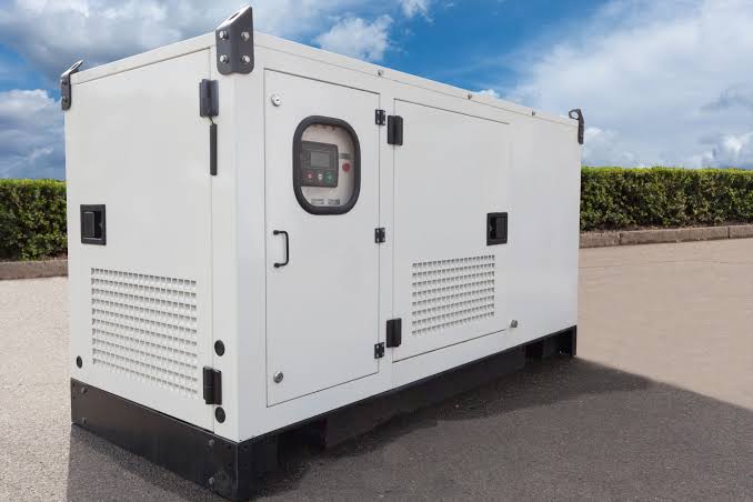
Critical Power Monitoring in Hospitals: What to Measure and Alarm
Learn how critical power monitoring hospital systems track voltage, current, power factor and breaker status to protect essential hospital electrical loads.
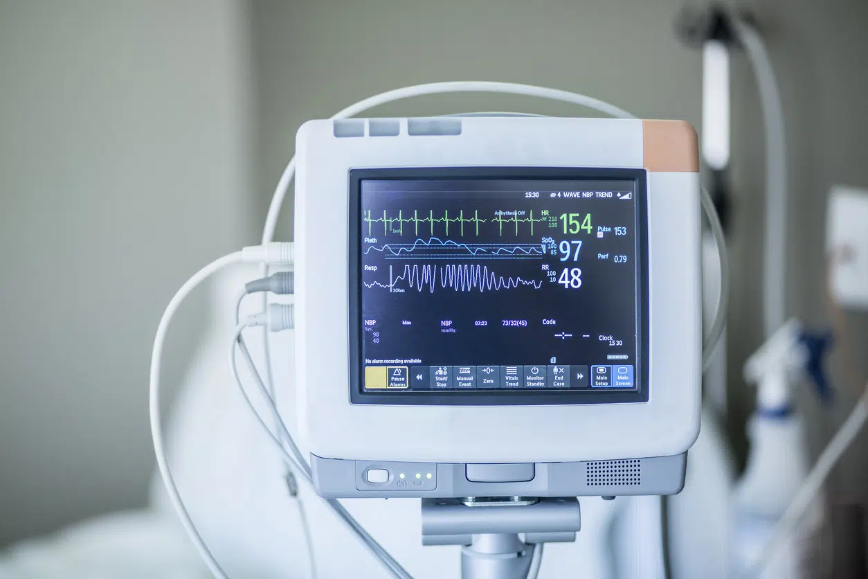
A critical power monitoring hospital system helps healthcare facilities monitor the electrical conditions of the distribution panels supplying operating theatres, intensive care units (ICUs), emergency departments, laboratories and other essential services.
Hospitals depend on stable electricity to operate medical equipment, lighting, ventilation, communications and essential building services. An electrical fault affecting one distribution panel can interrupt several connected systems, potentially affecting clinical operations and patient safety.
Related Products

ATS / MTS Kenya
ATS/MTS solutions from Paneltech Systems provide reliable Automatic and Manual Transfer Switches for seamless power transfer in industrial and commercial electrical systems.
View Product
Elmeasure
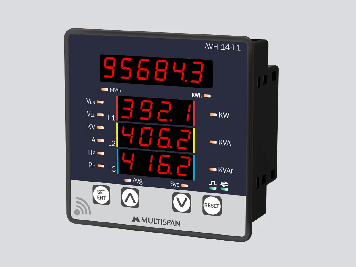
Elmeasure smart energy meters for comprehensive energy monitoring, measurement and management in commercial and industrial settings.
View Product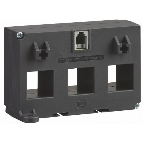
3 Phase Current Transformer
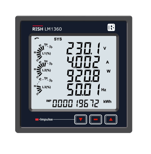
3-Phase Current Transformers for accurate power monitoring and measurement. Paneltech Systems offers high-quality Rishabh 3-Phase CTs for industrial energy monitoring and protection.
View Product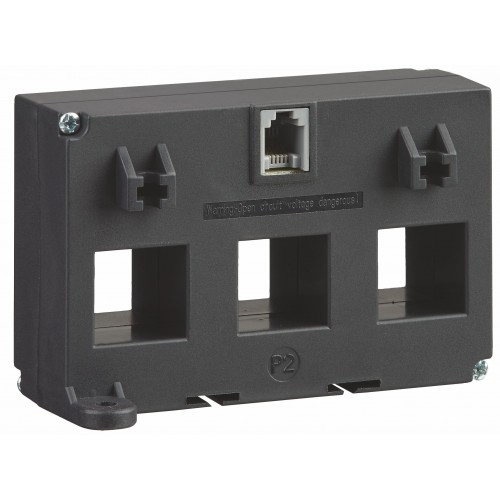
3 Phase RJ12
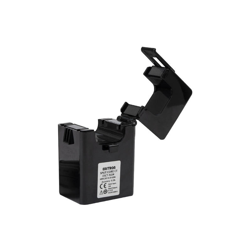
3-Phase RJ12 from Paneltech Systems for accurate power monitoring and efficient current measurement in industrial applications.
View ProductHowever, installing generators, uninterruptible power supplies (UPS) and automatic transfer switches (ATS) is only part of a reliable hospital electrical infrastructure. Facility managers also need visibility into what is happening inside the electrical distribution network.
A hospital energy monitoring system provides this visibility by measuring electrical parameters such as voltage, current, power factor, active power and energy consumption. Depending on the installed equipment, it can also monitor breaker positions, electrical faults and other operating conditions.
With appropriately configured alarms, maintenance personnel can investigate abnormal readings before they develop into more serious electrical problems.
Paneltech Systems Ltd provides electrical engineering and monitoring solutions for commercial and industrial facilities in Kenya. This guide explains what hospitals should measure, which alarms matter, how split-core current transformers simplify monitoring installations and how electrical monitoring supports preventive maintenance.
What Is Critical Power Monitoring in Hospitals?
Critical power monitoring is the continuous or periodic measurement of electrical conditions across distribution systems supplying important hospital equipment and services.
It involves installing monitoring instruments, current transformers, communication devices and monitoring software to collect information from selected electrical panels.
The information helps hospital engineers understand:
-
Whether electrical supplies remain within configured operating limits
-
How much current individual circuits or distribution feeders are drawing
-
Whether electrical loads are balanced across phases
-
Whether power factor is deteriorating
-
Whether a circuit breaker has changed operating state
-
Whether electrical consumption is increasing unexpectedly
-
Whether abnormal electrical conditions require investigation
A hospital critical power monitoring system can collect this information from several distribution boards and present it through a central monitoring interface.
For example, an engineering team may monitor the main low-voltage distribution board, generator supply, UPS distribution panels and selected downstream panels serving critical departments.
The objective is to improve visibility, identify developing problems and support informed maintenance decisions.
It is important to distinguish general electrical power monitoring from medical insulation monitoring. Medical isolated power systems in operating theatres and other designated medical locations require their own appropriate insulation monitoring and alarm arrangements.
These systems perform different but complementary functions.
Why Hospitals Need Critical Power Monitoring Systems
Hospital electrical systems are more complex than ordinary commercial building installations.
They contain several categories of electrical loads, different backup arrangements and specialised medical equipment that requires carefully managed power supplies.
Without adequate monitoring, maintenance teams may only discover problems after receiving a complaint, experiencing equipment failure or investigating an unexpected interruption.
A properly designed critical power monitoring hospital solution provides earlier visibility into changing electrical conditions.
1. Protecting Operating Theatres and ICUs
Operating theatres and intensive care units depend on reliable electrical infrastructure.
Medical equipment such as ventilators, patient monitors, surgical lighting, anaesthesia machines and other critical devices require appropriate electrical supplies.
Monitoring the distribution panels supplying these areas helps maintenance personnel identify abnormal voltage, excessive current and other electrical conditions.
For example, an increasing current reading on a distribution feeder may indicate a growing load or a developing equipment problem.
The engineering team can investigate the cause before it becomes an operational concern.
Monitoring does not replace medical-grade electrical protection, UPS systems or isolated power arrangements. It provides additional operational information.
2. Identifying Electrical Problems Earlier
An electrical installation can develop problems without immediately causing a complete outage.
Examples include:
-
Phase voltage imbalance
-
Uneven current distribution
-
Overloaded feeders
-
Declining power factor
-
Abnormal energy consumption
-
Excessive electrical demand
-
Unexpected breaker operations
Continuous measurement helps identify unusual changes in these parameters.
For example, if a panel normally operates within a relatively stable current range but begins drawing significantly more current, the monitoring system can flag the deviation for investigation.
The maintenance team can then inspect connected equipment, distribution circuits and operating conditions.
3. Improving Maintenance Planning
Hospitals often operate electrical systems continuously, making maintenance scheduling particularly important.
An energy monitoring system provides historical information that helps engineers understand how equipment performs over time.
The data can support:
-
Electrical load assessments
-
Maintenance scheduling
-
Identification of recurring abnormal conditions
-
Investigation of unexplained energy consumption
-
Electrical infrastructure upgrades
-
Distribution capacity planning
Rather than relying exclusively on occasional manual readings, maintenance teams can review recorded operating information when planning inspections.
4. Improving Visibility Across Multiple Distribution Panels
Large healthcare facilities may have several electrical distribution boards serving different departments.
Monitoring selected panels through a central interface allows engineers to compare electrical conditions across different parts of the facility.
For example, the team may compare the electrical demand of:
-
Operating theatre distribution panels
-
ICU distribution panels
-
Laboratory distribution boards
-
General ward distribution panels
-
HVAC distribution systems
-
Main LV distribution boards
This makes it easier to identify which areas experience higher demand and where further investigation may be necessary.
5. Supporting Energy Management
Electricity represents an important operating expense for hospitals.
An energy monitoring system helps facility managers understand how energy is consumed across different departments and equipment groups.
Historical consumption data can help identify:
-
Unexpected increases in consumption
-
High-demand operating periods
-
Poorly managed electrical loads
-
Opportunities for energy efficiency improvements
-
Changes in consumption after equipment upgrades
Energy management should never compromise the electrical reliability required by clinical services.
The purpose is to improve efficiency while maintaining appropriate power availability and safety.
7 Important Parameters to Measure in Hospital Electrical Panels
An effective critical power monitoring hospital installation should focus on parameters that help engineers assess the electrical condition of essential distribution systems.
The exact measurement requirements depend on the hospital's electrical design, equipment and monitoring objectives.
1. Voltage
Voltage monitoring helps determine whether the electrical supply remains within the configured operating range.
For three-phase hospital distribution systems, engineers should monitor:
-
Phase-to-phase voltage
-
Phase-to-neutral voltage, where applicable
-
Voltage imbalance
-
Voltage fluctuations
-
Under-voltage conditions
-
Over-voltage conditions
Abnormal voltage conditions can affect connected equipment and indicate problems with the supply or distribution network.
For example, persistent under-voltage may result in equipment malfunction, while excessive voltage can expose connected devices to damaging electrical conditions.
Voltage alarms should be configured according to the equipment ratings, supply characteristics and engineering requirements.
2. Current
Current measurement helps engineers understand how much electrical load is being drawn through a distribution panel or feeder.
Current monitoring is particularly useful for identifying:
-
Overloaded circuits
-
Increasing electrical demand
-
Uneven phase loading
-
Unexpected changes in load
-
Potential distribution capacity limitations
For example, a three-phase distribution board may show significantly higher current on one phase than the other two.
This imbalance can indicate unevenly distributed single-phase loads or another electrical issue requiring investigation.
Current transformers (CTs) are commonly used to measure current without connecting the monitoring instrument directly into the main power conductor.
3. Power Factor
Power factor indicates how effectively electrical power is being used by connected equipment.
A poor power factor can increase the current required to deliver a given amount of useful active power.
Hospitals contain numerous inductive loads, including:
-
Motors
-
Pumps
-
Air handling units
-
Chillers
-
Transformers
-
Compressors
These loads can contribute to reactive power demand.
Monitoring power factor helps facility managers understand whether the electrical system requires further investigation or power factor correction.
Where appropriate, an Automatic Power Factor Correction (APFC) panel can automatically switch capacitor banks to improve power factor.
However, capacitor selection and switching arrangements must account for the installation's harmonic conditions and load characteristics.
4. Active Power (kW)
Active power represents the electrical power converted into useful work, heat, light or other forms of energy.
Monitoring active power helps hospitals understand the actual electrical demand of different distribution panels.
It can be used to assess:
-
Peak electrical demand
-
Department-level consumption
-
Equipment operating patterns
-
Changes in electrical loading
-
Demand after equipment installation
For example, an increase in active power demand may occur when additional medical equipment or HVAC systems are introduced.
Monitoring allows the engineering team to observe these changes and assess whether the distribution infrastructure remains suitable.
5. Reactive Power (kVAr)
Reactive power is associated with the magnetic and electric fields required by certain electrical equipment.
Although it does not represent useful active energy consumption in the same way as kW, it contributes to electrical system current and affects power factor.
Hospitals with substantial motor and transformer loads may benefit from monitoring reactive power.
This information can help engineers evaluate:
-
Reactive power demand
-
Power factor performance
-
Capacitor bank operation
-
Changes in inductive loading
-
The effectiveness of correction equipment
When combined with active power measurements, reactive power monitoring provides a more complete picture of electrical system performance.
6. Energy Consumption (kWh)
Energy consumption measures how much electrical energy a system uses over time.
It is particularly useful for hospital facility managers responsible for energy budgeting and operational efficiency.
Monitoring energy consumption across selected distribution panels can help identify which departments or services account for significant electricity usage.
Historical kWh readings can also support comparisons between different operating periods.
For meaningful analysis, monitoring points should be configured consistently and assigned to clearly identified distribution boards or circuits.
7. Breaker Status
Breaker status monitoring provides information about whether selected circuit breakers are open, closed or have changed operating state.
This can help engineers investigate unexpected electrical interruptions.
For example, if a breaker supplying a critical distribution panel opens unexpectedly, a monitoring system connected to its auxiliary contacts may communicate that status to a central interface.
This allows the engineering team to identify the affected distribution point more quickly.
However, breaker status monitoring requires compatible auxiliary contacts or an appropriate communication interface. It should not be assumed that every standard monitoring meter can detect breaker position independently.
Monitoring equipment should observe the electrical protection system rather than interfere with its protective operation.
Understanding a Split-Core Panelboard Monitoring System
One important consideration when introducing monitoring into an existing hospital is avoiding unnecessary disruption to electrical services.
Hospitals cannot always afford lengthy shutdowns of operational distribution boards.
A split-core panelboard monitoring system provides a practical way to introduce current measurement into existing electrical installations.
What Is a Split-Core Current Transformer?
A split-core current transformer is a device designed to measure alternating current flowing through an electrical conductor.
Unlike a conventional solid-core CT, a split-core CT has an opening mechanism that allows the magnetic core to be placed around an existing conductor.
The core is then closed and secured according to the manufacturer's installation instructions.
This design can simplify the installation of monitoring equipment in existing electrical panels because the conductor does not normally need to be disconnected or removed to install the CT.
How Split-Core CTs Work
A split-core CT works through electromagnetic induction.
When alternating current flows through the conductor passing through the CT, it produces a changing magnetic field.
The CT detects this magnetic field and generates a corresponding secondary current or signal that can be interpreted by a compatible monitoring instrument.
The monitoring meter uses the CT ratio and configuration to calculate the primary current.
For example, a CT with a specified 100:5 ratio is designed to represent a primary current of 100 A as a secondary current of 5 A under its rated operating conditions.
The actual CT ratio must be matched to the connected meter and expected load.
Advantages of Split-Core CTs in Existing Hospitals
Split-core CTs offer several practical advantages.
Reduced installation disruption
They can often be installed around existing conductors without disconnecting the conductor itself.
Simplified retrofitting
Existing distribution boards can be upgraded with current monitoring without necessarily replacing the complete panel.
Flexible installation
Different CT sizes and ratings are available for different conductor arrangements and measurement requirements.
Improved visibility
They allow selected feeders to be included in an energy monitoring system.
Scalable monitoring
Additional monitoring points can be introduced as the hospital expands its electrical monitoring programme.
However, split-core CT installation is not automatically a shutdown-free or risk-free activity.
Opening an energised electrical panel can expose technicians to serious electrical hazards. Installation must be assessed and carried out by appropriately qualified personnel using approved safe working procedures. Some installations may require isolation or a planned outage.
CT secondary circuits must also be installed and handled according to the manufacturer's safety instructions. In particular, conventional current-output CT secondary circuits must not be left open-circuited while the primary conductor is energised.
How a Hospital Energy Monitoring System Works
A typical hospital electrical monitoring system consists of several connected components.
1. Current Transformers
CTs measure current flowing through selected electrical feeders.
The CT specification must match the expected current range, conductor arrangement and monitoring instrument.
2. Voltage Measurement Connections
Voltage inputs allow compatible monitoring meters to measure the electrical supply.
These connections must be designed with appropriate fusing, isolation and protection.
3. Multifunction Power Meters
Multifunction meters process electrical measurements and calculate parameters such as:
-
Voltage
-
Current
-
Frequency
-
Active power
-
Reactive power
-
Power factor
-
Energy consumption
Some models also provide power quality measurements and communication functions.
4. Communication Infrastructure
Monitoring devices may communicate through interfaces such as:
-
Modbus RTU over RS-485
-
Modbus TCP
-
Ethernet
-
Other manufacturer-supported protocols
The communication arrangement depends on the selected monitoring equipment and the hospital's existing building management or supervisory control infrastructure.
5. Monitoring Software
The software collects information from the meters and displays it through dashboards, reports and historical trends.
Maintenance teams can use the interface to compare electrical parameters across selected distribution boards.
6. Alarm and Notification System
The monitoring system compares measurements against configured thresholds and operating conditions.
When an abnormal condition occurs, it can generate an alarm for authorised personnel.
Notifications may appear through a central dashboard, local display or other supported communication channels.
What Electrical Alarms Should Hospitals Configure?
Monitoring measurements become more useful when the system can identify abnormal conditions and communicate them clearly.
Alarm configuration should reflect the hospital's electrical design and the importance of the monitored load.
The following table provides examples of useful monitoring alarms.
| Alarm | What it indicates | Recommended response |
|---|---|---|
| Under-voltage | Supply voltage below configured limits | Investigate incoming supply and distribution |
| Over-voltage | Supply voltage above configured limits | Check supply conditions and voltage regulation |
| Overcurrent | Current exceeds the configured threshold | Investigate loading and protection coordination |
| Phase imbalance | Significant difference between phase measurements | Review load distribution and supply conditions |
| Low power factor | Power factor falls below the configured target | Investigate reactive loads and correction equipment |
| High demand | Electrical demand exceeds the planned operating range | Review connected loads and capacity |
| Breaker trip/status change | Monitored breaker changes position | Identify affected circuit and investigate |
| Communication failure | Monitoring device stops communicating | Check power, wiring and network connections |
| Abnormal energy consumption | Consumption differs significantly from expected patterns | Investigate operational changes and connected equipment |
Alarm thresholds should not be copied blindly from another hospital.
They should be established using equipment specifications, electrical system design, operating history and engineering assessments.
Prioritising Critical Alarms
Not every alarm requires the same response.
Hospitals should consider classifying monitoring alerts into categories.
Critical alarms
These relate to conditions that may affect essential electrical distribution or require immediate technical investigation.
High-priority alarms
These indicate abnormal electrical conditions requiring prompt attention.
Advisory alarms
These identify changes that should be reviewed during routine maintenance or engineering assessments.
Alarm escalation should identify who receives the notification, how quickly they should respond and what procedure they should follow.
The monitoring system should also record alarm acknowledgements and subsequent actions where supported.
Critical Power Monitoring Versus Medical Insulation Monitoring
This distinction is especially important when designing hospital electrical systems.
A general power monitoring system measures electrical parameters such as voltage, current, power factor and energy consumption.
A medical insulation monitoring system performs a different safety function within an isolated medical IT system.
In designated medical locations, such as certain operating theatres, an isolated power supply may use a medical isolation transformer and a medical insulation monitoring device.
The monitoring device checks the insulation condition between the isolated supply conductors and earth.
When an insulation fault develops, it provides an alarm so that technical personnel can investigate while the supply arrangement maintains the required continuity under applicable system conditions.
The two systems should not be treated as interchangeable.
| Feature | General power monitoring | Medical insulation monitoring |
|---|---|---|
| Main purpose | Monitor electrical operating conditions | Monitor insulation condition in medical IT systems |
| Typical measurements | Voltage, current, kW, kVAr, power factor, kWh | Insulation resistance and related medical IT conditions |
| Installation | Selected distribution boards and feeders | Medical isolated power systems |
| Main users | Facility engineers and maintenance teams | Biomedical and electrical maintenance personnel |
| Alarm examples | Overcurrent, voltage deviation, breaker status | Insulation fault, transformer overload or temperature |
| Primary objective | Visibility and operational management | Medical electrical safety and fault warning |
IEC 60364-7-710 addresses electrical installation requirements for medical locations, while medical insulation monitoring devices are covered by the relevant IEC 61557 requirements.
Hospitals should ensure that general energy monitoring supplements rather than replaces the required medical electrical safety systems.
Integrating Monitoring With Hospital UPS, ATS and Generator Systems
Critical power monitoring becomes more useful when it provides visibility into the different parts of a hospital's power infrastructure.
A typical hospital may have:
-
KPLC utility supply
-
Standby diesel generators
-
Automatic transfer switches
-
UPS systems
-
Main low-voltage distribution boards
-
Essential services distribution panels
-
Medical isolated power systems
-
Downstream distribution boards
Monitoring selected points across this arrangement can help engineers understand electrical conditions before and after power source transfers.
For example, monitoring may show changes in voltage, current and power demand when a hospital transfers from utility supply to generator power.
The engineering team can review whether the monitored electrical conditions remain within the expected operating range.
Breaker auxiliary contacts and supported communication interfaces can also provide information about switching equipment status.
Hospitals should coordinate monitoring with the existing protection and control architecture to avoid introducing unwanted interference.
Read more about hospital ATS panels and uninterrupted power supply.
For medical isolated distribution requirements, see our guide to hospital isolated power supply panels.
Planning a Critical Power Monitoring Hospital Installation
A successful monitoring project starts with understanding the existing electrical infrastructure.
Hospitals should not install meters and CTs without first identifying which electrical parameters need to be monitored and why.
Step 1: Conduct an Electrical Distribution Assessment
Identify the main distribution boards, essential services panels and critical feeders.
Review the single-line diagrams and establish how power moves through the hospital.
This helps determine the most useful monitoring points.
Step 2: Identify Critical Loads
Determine which electrical systems require close monitoring.
These may include operating theatres, ICUs, emergency departments, laboratories, imaging equipment and other essential services.
The actual monitoring arrangement should follow the hospital's load classification and engineering requirements.
Step 3: Select Suitable Monitoring Instruments
Choose multifunction meters, CTs and communication equipment according to:
-
Rated voltage
-
Expected current
-
Measurement accuracy
-
CT compatibility
-
Communication requirements
-
Environmental conditions
-
Required alarm functions
The instruments must be compatible with the existing electrical system.
Step 4: Assess Existing Panelboards
Review the available physical space, busbar and conductor arrangements, enclosure conditions and safety requirements.
For existing panels, split-core CTs may offer a convenient retrofitting option where the conductor arrangement permits.
Step 5: Design the Monitoring Network
Establish how monitoring instruments will communicate with the central monitoring system.
Define device addresses, communication protocols, data collection intervals and alarm destinations.
Step 6: Configure Alarms and Dashboards
Set appropriate thresholds for voltage, current, power factor, demand and other monitored parameters.
Create dashboards that make it easy for engineering personnel to identify the location and nature of an abnormal condition.
Step 7: Test and Commission the System
Verify measurement accuracy, CT ratios, phase identification, communication performance and alarm operation.
Confirm that readings correspond with the actual electrical installation.
Step 8: Train Maintenance Personnel
Ensure authorised personnel understand how to interpret measurements, acknowledge alarms and escalate abnormal conditions.
Monitoring is most useful when the people responsible for electrical maintenance know how to respond to the information.
How Critical Power Monitoring Supports Preventive Maintenance
Preventive maintenance is essential for hospitals because electrical problems can affect equipment availability and service continuity.
Monitoring information can help maintenance teams identify developing trends rather than waiting for an obvious failure.
For example, engineers may observe:
-
A gradual increase in current demand
-
Repeated phase imbalance
-
A deterioration in power factor
-
Increasing energy consumption
-
Repeated breaker status changes
-
Abnormal voltage conditions
These observations can guide further inspections and testing.
However, electrical monitoring alone cannot identify every fault.
Thermal imaging, insulation testing, physical inspection, protection testing and other maintenance procedures remain important.
A comprehensive maintenance programme combines monitoring data with scheduled inspections and appropriate electrical testing.
Choosing the Right Hospital Power Monitoring Solution in Kenya
Hospitals planning an electrical monitoring upgrade should consider more than the purchase price of meters and CTs.
The selected solution should suit the facility's electrical infrastructure and operational requirements.
Important considerations include:
Measurement requirements: Decide whether the project requires voltage, current, power factor, energy, power quality and breaker status monitoring.
Monitoring coverage: Determine which distribution boards and feeders need to be included.
Retrofit compatibility: Check whether existing panels can accommodate the selected CTs and instruments.
Communication compatibility: Ensure monitoring devices can communicate with the proposed central system.
Alarm management: Establish who receives alerts and how technical personnel should respond.
Expansion capability: Select a system that can accommodate additional monitoring points as the hospital grows.
Technical support: Confirm whether the supplier can assist with design, equipment selection, installation and commissioning.
Paneltech Systems provides electrical panel and monitoring-related solutions for commercial and industrial installations in Kenya.
Hospitals can also explore low-voltage electrical panel solutions when planning distribution upgrades.
Why Work With Paneltech Systems?
Hospital electrical infrastructure requires careful planning, suitable equipment and an understanding of the operational requirements of healthcare facilities.
Paneltech Systems Ltd works with electrical distribution, automation and monitoring-related equipment for industrial and commercial applications.
Its areas of work include:
-
Low-voltage electrical panels
-
Hospital electrical distribution solutions
-
Automatic and manual transfer switch systems
-
Automatic power factor correction panels
-
Variable frequency drives
-
Electrical measurement and monitoring equipment
For hospitals planning to improve electrical visibility, the first step is identifying the distribution boards and parameters that require monitoring.
Paneltech Systems can assist with discussing equipment requirements and identifying suitable monitoring options.
The final design should be reviewed by appropriately qualified electrical professionals and coordinated with the hospital's biomedical engineering and facilities teams.
Frequently Asked Questions About Critical Power Monitoring in Hospitals
1. What is critical power monitoring in hospitals?
Critical power monitoring in hospitals is the measurement and supervision of electrical conditions across distribution panels supplying essential healthcare services. It tracks parameters such as voltage, current, power factor, energy consumption and, where supported, breaker status. The information helps engineers identify abnormal electrical conditions and plan maintenance.
2. What parameters should hospitals monitor in electrical panels?
Hospitals should consider monitoring phase voltage, current, frequency, active power, reactive power, power factor and energy consumption. Breaker status, phase imbalance and selected power quality parameters may also be monitored depending on the installation.
3. What is a split-core panelboard monitoring system?
A split-core panelboard monitoring system uses split-core current transformers to measure current in existing electrical distribution panels. The CTs can be fitted around suitable existing conductors without normally disconnecting the conductor, making them useful for certain monitoring retrofit projects.
4. Can split-core CTs be installed without shutting down a hospital?
Split-core CTs can often be installed without disconnecting the monitored conductor. However, opening an energised electrical panel still presents serious hazards. Whether installation can proceed without shutdown depends on the panel design, risk assessment, safe working procedures and applicable electrical safety requirements. Some installations require isolation.
5. How does an energy monitoring system help hospitals?
A hospital energy monitoring system provides information about electrical consumption and operating conditions across selected distribution panels. It helps facility managers identify abnormal demand, monitor power factor, review energy consumption and plan maintenance.
6. What alarms should a hospital electrical monitoring system have?
Useful alarms include under-voltage, over-voltage, overcurrent, phase imbalance, low power factor, excessive demand, breaker status changes and communication failures. Alarm thresholds should be established according to the hospital's electrical design and equipment requirements.
7. What is the difference between power monitoring and insulation monitoring?
Power monitoring measures electrical parameters such as voltage, current, power and energy consumption. Insulation monitoring checks the insulation condition of medical isolated power systems. Both are important in appropriate hospital installations, but they perform different functions.
8. Can hospital power monitoring be connected to a BMS or SCADA system?
Yes. Compatible multifunction meters and monitoring devices can communicate with building management systems or SCADA platforms through supported protocols such as Modbus RTU or Modbus TCP. Compatibility and integration requirements should be confirmed during system design.
9. Does critical power monitoring replace hospital UPS and ATS systems?
No. Monitoring systems provide measurement, visibility and alarms. UPS systems provide backup power, while ATS systems manage power source transfer. Monitoring complements these systems but does not replace their functions.
10. Where can hospitals get electrical monitoring solutions in Kenya?
Hospitals can contact Paneltech Systems Ltd in Nairobi to discuss electrical distribution, monitoring equipment and panel requirements. Visit https://paneltechsystems.co.ke/ to make an enquiry.
Get Critical Power Monitoring Solutions for Your Hospital
A hospital electrical monitoring system provides valuable information about the condition and performance of essential electrical distribution networks.
By measuring voltage, current, power factor, energy consumption and breaker status, facility managers can improve electrical visibility and support more effective maintenance planning.
Split-core CTs can make monitoring upgrades easier in suitable existing panelboards, while central dashboards and configured alarms help technical personnel identify abnormal conditions.
For hospitals in Kenya considering a new monitoring installation or an upgrade to existing distribution panels, Paneltech Systems Ltd can help assess the equipment and monitoring requirements.
Contact Paneltech Systems Ltd
Website: https://paneltechsystems.co.ke/
Location: Nairobi, Kenya
Request a technical consultation and discuss your hospital's electrical monitoring requirements.